Neopixel Lightsaber
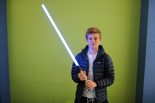
For my main project, the NeoPixel Lightsaber, I completed two milestones on my path to a finished project. These milestones are documented below with videos and notes. There are 3 components to the NeoPixel Lightsaber: the hilt, the electronics, and the neopixel blade. The neopixel controlled by an arduino nano that dictates the LED patterns in the blade. The hilt encases the Arduino and other components.
| Engineer | School | Area of Interest | Grade |
|---|---|---|---|
|
Walter W. |
Acalanes High School |
|
Rising Junior |
SECOND MILESTONE
For my second milestone, I put together the entire lightsaber blade and inserted the neopixels along with the Arduino and other components. This process involved a lot of soldering, sawing, taping and twisting. There was much more of a focus on construction rather than the coding and electrical work which was very relevant to reach the first milestone. I encountered many challenges while reaching this milestone, including electrical shorts; minimal instructions; and lack of correct equipment, space and time. By the second milestone, I learned how to overcome problems without looking at a guide to get me through them.
FIRST MILESTONE
My First Milestone for the Neopixel Lightsaber was to have working electrical components. This means that I moved all of my wires and components from a breadboard to a free-floating circuit. I had to do this in order to fit everything into the hilt of the lightsaber. This process was difficult because I had to look at both the original schematic for the project and my breadboard to make the circuit because I made multiple modifications to make use of the materials we had at the workshop. Although this took some time and effort, it made the build cheaper and unique.
#include “FastLED.h”
#if defined(FASTLED_VERSION) && (FASTLED_VERSION < 3001000)
#warning “Requires FastLED 3.1 or later; check github for latest code.”
#endif
#define LED_PIN 8
#define LED_TYPE WS2812
#define COLOR_ORDER GRB
#define NUM_LEDS 129
#define switchPin 5
CRGB leds[NUM_LEDS];
#define BRIGHTNESS 250
#define FRAMES_PER_SECOND 120
int saber_height = 0;
int prev_pos = 0;
int temp_pos = 0;
int pulse_center = 30;
int oldMode = 0; // assume switch closed because of pull-down resistor
const unsigned long debounceTime = 1000; // milliseconds
/*Not really used yet. Thought to be able to switch between sound reactive
mode, and general gradient pulsing/static color*/
int mode = 0;
//For Fire
#define SPARKING 300
#define COOLING 45
bool gReverseDirection = false;
#define FRAMES_PER_SECOND 180
void saber_on();
//config for balls
#define GRAVITY -9.81 // Downward (negative) acceleration of gravity in m/s^2
#define h0 1 // Starting height, in meters, of the ball (strip length)
#define NUM_BALLS 6 // Number of bouncing balls you want (recommend < 7, butx 20 is fun in its own way)
#define NUM_BALLS_2 3 // Number of bouncing balls you want (recommend < 7, butx 20 is fun in its own way)
float h[NUM_BALLS] ; // An array of heights
float h_2[NUM_BALLS_2] ; // An array of heights
float vImpact0 = sqrt( -2 * GRAVITY * h0 ); // Impact velocity of the ball when it hits the ground if “dropped” from the top of the strip
float vImpact[NUM_BALLS] ; // As time goes on the impact velocity will change, so make an array to store those values
float tCycle[NUM_BALLS] ; // The time since the last time the ball struck the ground
int pos[NUM_BALLS] ; // The integer position of the dot on the strip (LED index)
int pos_2[NUM_BALLS] ; // The integer position of the dot on the strip (LED index)
long tLast[NUM_BALLS] ; // The clock time of the last ground strike
float COR[NUM_BALLS] ; // Coefficient of Restitution (bounce damping)
void setup() {
pinMode (switchPin, INPUT);
delay(1000); // 3 second delay for recovery
// Serial.begin(9600);
// tell FastLED about the LED strip configuration
FastLED.addLeds(leds, NUM_LEDS).setCorrection(TypicalLEDStrip);
// set master brightness control
FastLED.setBrightness(BRIGHTNESS);
FastLED.setMaxPowerInVoltsAndMilliamps(5,2000);
delay(1000);
for (int i = 0 ; i < NUM_BALLS ; i++) { // Initialize variables
tLast[i] = millis();
h[i] = h0;
pos[i] = 0; // Balls start on the ground
vImpact[i] = vImpact0; // And “pop” up at vImpact0
tCycle[i] = 0;
COR[i] = 0.90 – float(i)/pow(NUM_BALLS,2);
}
}
// List of patterns to cycle through. Each is defined as a separate function below.
typedef void (*SimplePatternList[])();
SimplePatternList gPatterns = {Balls, blur, confetti, sinelon, juggle, bpm };
uint8_t gCurrentPatternNumber = 0; // Index number of which pattern is current
uint8_t gHue = 150; // rotating “base color” used by many of the patterns
void loop()
{
// see if switch is open or closed
int switchState = digitalRead (switchPin);
// has it changed since last time?
if (switchState == 0)
{
delay(300);
if (oldMode == 3)
{
oldMode = 0;
gHue = 150;
} // end if switchState is LOW
else {
oldMode++;
}
} // end of state change
switch(oldMode) {
case 0:
saber_on();
break;
case 1:
saber_off();
break;
case 2:
pattern_rotate();
break;
case 3:
saber_off();
break;
default:
break;
}
}
#define ARRAY_SIZE(A) (sizeof(A) / sizeof((A)[0]))
void nextPattern()
{
// add one to the current pattern number, and wrap around at the end
gCurrentPatternNumber = (gCurrentPatternNumber + 1) % ARRAY_SIZE( gPatterns);
}
void saber_on() {
if (saber_height == 0) {
for (int i = 0; i < NUM_LEDS-10; i = i+2) {
leds[i] = CHSV( gHue, 250, 220);
leds[i+1] = CHSV( gHue, 250, 180);
leds[i+2] = CHSV( gHue, 250, 120);
leds[i+3] = CHSV( gHue, 250, 80);
leds[i+4] = CHSV( gHue, 250, 50);
leds[i+5] = CHSV( gHue, 250, 20);
FastLED.show();
delay(3);
}
saber_height = 1;
// delay(50);
// for (int j =0; j < NUM_LEDS_2; j++) {
// leds_2[j] = CRGB(gHue, 250, 220);
// FastLED.show();
// }
}
else {
int pos = beatsin16( 8, 230, 250);
int pos_2 = beatsin16(15, 180, 220);
for (int i = 0; i < NUM_LEDS; i++) { leds[i] = CHSV( 150, pos, pos_2); } } FastLED.show(); } void saber_off() { if (saber_height == 1) { for (int i = NUM_LEDS-1; i > 6; i = i-2) {
leds[i-5] = CHSV( gHue, 250, 150);
leds[i-4] = CHSV( gHue, 250, 120);
leds[i-3] = CHSV( gHue, 250, 100);
leds[i-2] = CHSV( gHue, 250, 60);
leds[i-1] = CHSV( gHue, 250, 30);
leds[i] = CHSV( 0, 0, 0);
FastLED.show();
}
saber_height = 0;
}
else {
for (int i = 0; i < NUM_LEDS; i++) {
leds[i] = CHSV( 0, 0, 0);
}
}
FastLED.show();
}
void pattern_rotate() {
// Call the current pattern function once, updating the ‘leds’ array
gPatterns[gCurrentPatternNumber]();
// send the ‘leds’ array out to the actual LED strip
FastLED.show();
// insert a delay to keep the framerate modest
FastLED.delay(1000/FRAMES_PER_SECOND);
// do some periodic updates
EVERY_N_MILLISECONDS( 5 ) { gHue++; } // slowly cycle the “base color” through the rainbow
EVERY_N_SECONDS( 10 ) { nextPattern(); } // change patterns periodically
}
void rainbow()
{
// FastLED’s built-in rainbow generator
fill_rainbow( leds, NUM_LEDS-1, gHue, 7);
}
void rainbowWithGlitter()
{
// built-in FastLED rainbow, plus some random sparkly glitter
rainbow();
addGlitter(80);
}
void addGlitter( fract8 chanceOfGlitter)
{
if( random8() < chanceOfGlitter) {
leds[ random16(NUM_LEDS-1) ] += CRGB::White;
}
}
void confetti()
{
// random colored speckles that blink in and fade smoothly
fadeToBlackBy( leds, NUM_LEDS, 10);
int pos = random16(NUM_LEDS-1);
leds[pos] += CHSV( gHue + random8(64), 200, 240);
}
void sinelon()
{
// a colored dot sweeping back and forth, with fading trails
fadeToBlackBy( leds, NUM_LEDS, 8);
int pos = beatsin16( 40, 0, NUM_LEDS-1 );
leds[pos] += CHSV( gHue, 255, 192);
}
void bpm()
{
// colored stripes pulsing at a defined Beats-Per-Minute (BPM)
uint8_t BeatsPerMinute = 62;
CRGBPalette16 palette = PartyColors_p;
uint8_t beat = beatsin8( BeatsPerMinute, 64, 230);
for( int i = 0; i < NUM_LEDS; i++) { //9948
leds[i] = ColorFromPalette(palette, gHue+(i*2), beat-gHue+(i*10));
}
}
void juggle() {
// eight colored dots, weaving in and out of sync with each other
fadeToBlackBy( leds, NUM_LEDS, 20);
byte dothue = 0;
for( int i = 0; i < 8; i++) {
leds[beatsin16( i+7, 0, NUM_LEDS-1 )] |= CHSV(dothue, 200, 230);
dothue += 32;
}
}
void blur() {
uint8_t blurAmount = dim8_raw( beatsin8(3,64, 192) ); // A sinewave at 3 Hz with values ranging from 64 to 192.
blur1d( leds, NUM_LEDS, blurAmount); // Apply some blurring to whatever’s already on the strip, which will eventually go black.
uint8_t i = beatsin8( 9, 0, NUM_LEDS-1);
uint8_t j = beatsin8( 7, 0, NUM_LEDS-1);
uint8_t k = beatsin8( 5, 0, NUM_LEDS-1);
// The color of each point shifts over time, each at a different speed.
uint16_t ms = millis();
leds[(i+j)/2] = CHSV( ms / 29, 200, 220);
leds[(j+k)/2] = CHSV( ms / 41, 200, 220);
leds[(k+i)/2] = CHSV( ms / 73, 200, 220);
leds[(k+i+j)/3] = CHSV( ms / 53, 200, 220);
FastLED.show();
} // loop()
void Balls() {
for (int i = 0 ; i < NUM_BALLS ; i++) {
tCycle[i] = millis() – tLast[i] ; // Calculate the time since the last time the ball was on the ground
// A little kinematics equation calculates positon as a function of time, acceleration (gravity) and intial velocity
h[i] = 0.5 * GRAVITY * pow( tCycle[i]/1000 , 2.0 ) + vImpact[i] * tCycle[i]/1000;
if ( h[i] < 0 ) {
h[i] = 0; // If the ball crossed the threshold of the “ground,” put it back on the ground
vImpact[i] = COR[i] * vImpact[i] ; // and recalculate its new upward velocity as it’s old velocity * COR
tLast[i] = millis();
if ( vImpact[i] < 0.01 ) vImpact[i] = vImpact0; // If the ball is barely moving, “pop” it back up at vImpact0
}
pos[i] = round( h[i] * (NUM_LEDS – 1) / h0); // Map “h” to a “pos” integer index position on the LED strip
}
//Choose color of LEDs, then the “pos” LED on
for (int i = 0 ; i < NUM_BALLS ; i++) {
leds[pos[i]] = CHSV( uint8_t (i * 40) , 255, 220);
}
FastLED.show();
//Then off for the next loop around
for (int i = 0 ; i < NUM_BALLS ; i++) {
leds[pos[i]] = CRGB::Black;
}
}
STARTER PROJECT
My Starter Project was the MintyBoost portable charger. This was a battery-powered charger which fit inside an Altoids tin. It was very simple to make and introduced me to soldering and the basics of electrical work. There were many components such as resistors and capacitors which were completely new to me and fun to work with.
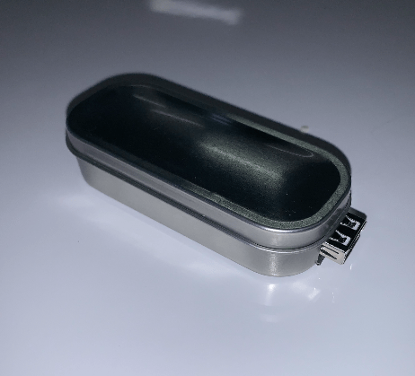
HOW IT WORKS
The MintyBoost is powered by an AA battery back which has an output of 3 volts. The power from the battery pack runs into the circuit controlled by an IC chip. This IC chip controls the circuit via a switch which will force the current down two different paths. If the switch is closed, the current will go through an inductor which increase energy via magnetic field. The goal of the inductor is to increase the voltage to the 5 volts required to power a USB port which the MintyBoost uses to charge electronics. When the current reaches 5 volts, the switch is opened, and the current goes through to 2 ceramic capacitors to smooth out the circuit and prevent large power fluctuations. This line also forces the current through to the USB port where a USB type charger can be plugged in and supplied power.