Sharad P. | BlueStamp Engineering

Sharad P.

Gesture-Controlled 3D Robotic Hand

Mimic is a 3D printed hand which mimics the finger movement of the user using flex sensors & servos.
Engineer School Area of Interest Grade
Sharad P.
Gunn High School
Electrical Engineering/Computer Science
Rising Freshman

THIRD MILESTONE + MODIFICATIONS

The majority of the time alocated for my Third Milestone was spent in finetuning my project since the code was already completed in the First Milestone and the hardware in the Second Milestone. I did, however attach my flex sensors to my glove using electrical tape. Not only did the tape secure the flex sensors onto my fingers, but also secured the connections from my arduino to my flex sensor. Previously, many of the connections fell out and failed to supply the power to the flex sensors. The one change I made to my code was that I calibrated the new flex sensor resistance values, since they had changed from the First Milestone( In the beginning, the flex sensors were perpendicularly attached to the breadboard, for my third milestone however, it was comnnected to my fingers which had a slight natural bend) To get the right flex sensor values I used the serial plotter which plotted out the points fed to it from ‘Serial.println()’ on a graph. 

Decrease In Voltage, Sensed By The Analog Pins On The Arduino.

After completing my project, I did re-visit some of the earlier concepts to grasp a more thorough understanding of my circuit. When looking at my circuit, I had to resistors- the flex sensor(variable resistor) and a normal 22k Ω. I had initially took this as a given and simply went with it. However, after some indepedent research, I figured that if I had the flex sensor as the only resistor, my arduino would always read the voltage to be 0, since the flex sensor which essentially eat up all the voltage. However, if I introduced a second resistor in series the input voltage would be divided across the two resistors and the voltage read by the arduino would be a fraction of the original input voltage based on the bend of the flex sensor. This phenomenon is called a voltage divide. To derive the voltage divide you have to use Ohms Law; Volgtage = Current x Resistance. Since the resistance increases by adding another resistor, and the voltage is the same, the overall current decreases. That’s why the voltage across the first resistor(the flex sensor) is less than the original input voltage, and thus the voltage is divided.


Diagram Of Wireless Modification.

SECOND MILESTONE

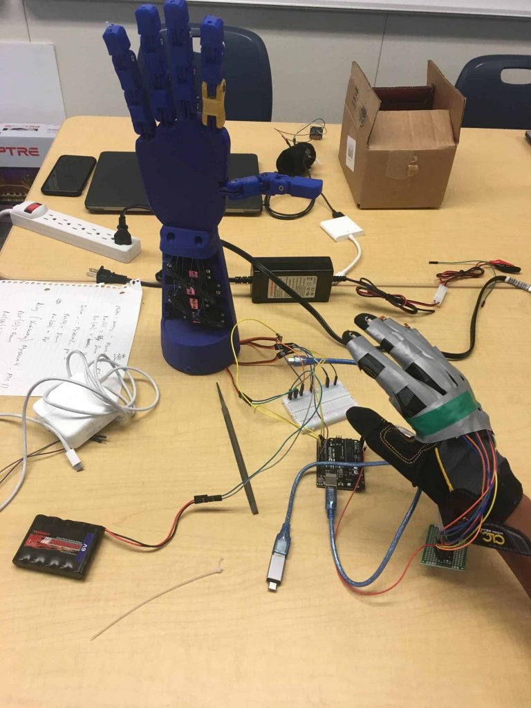
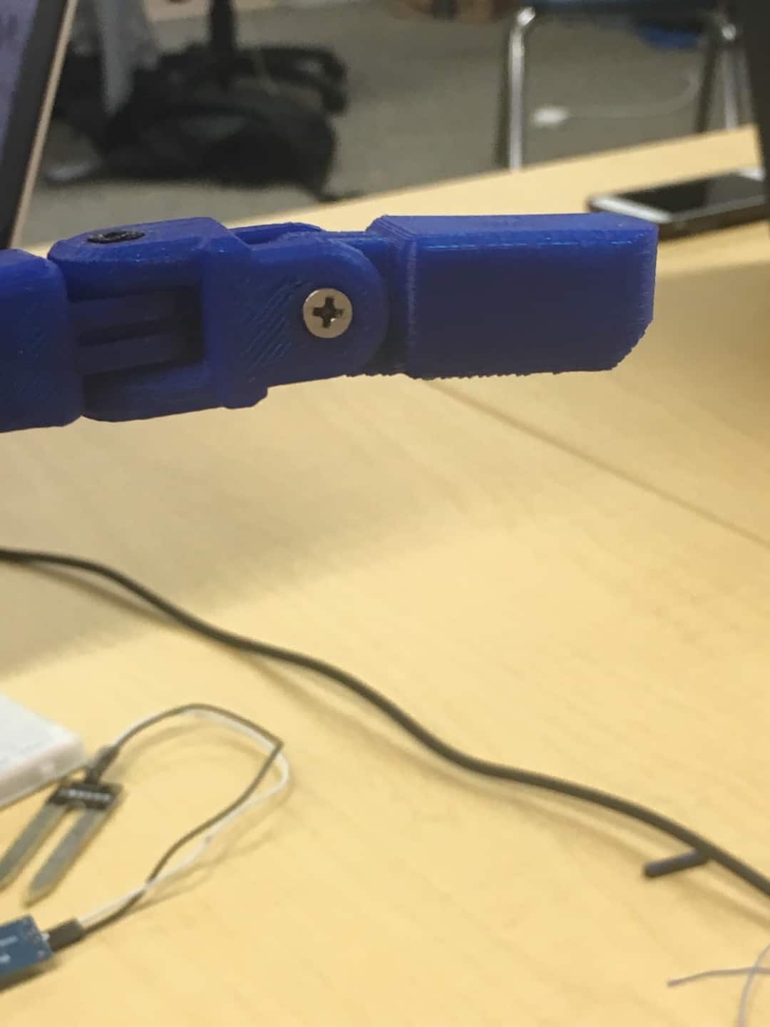
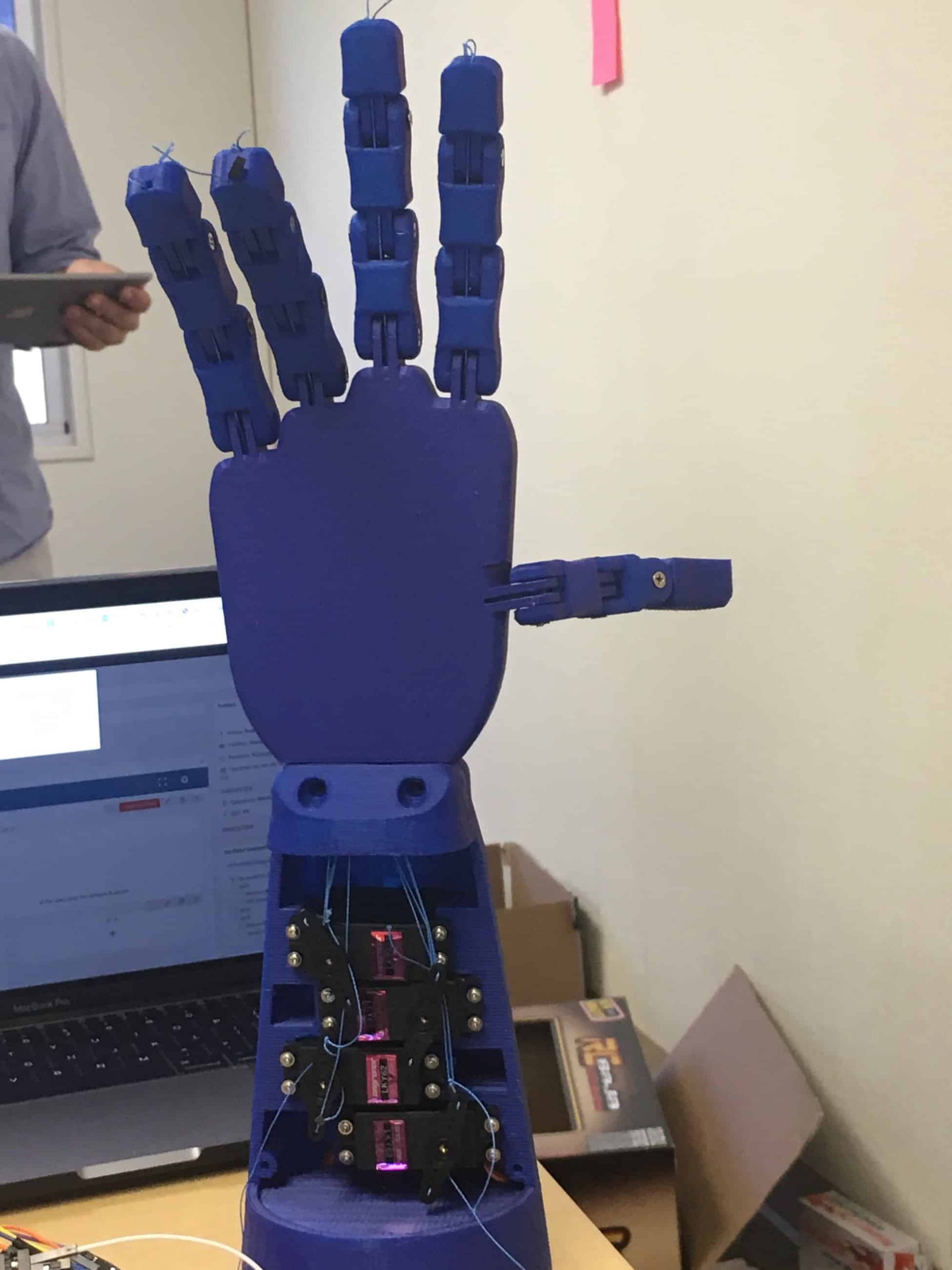
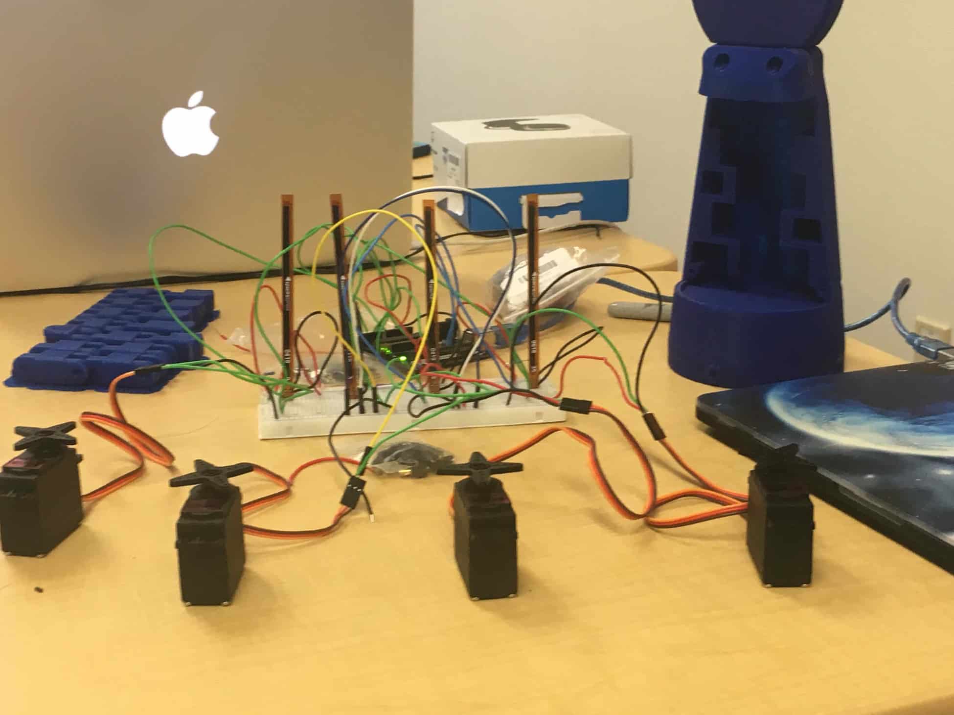
For my second milestone I decided to showcase a fully assembled 3D printed hand and base. 
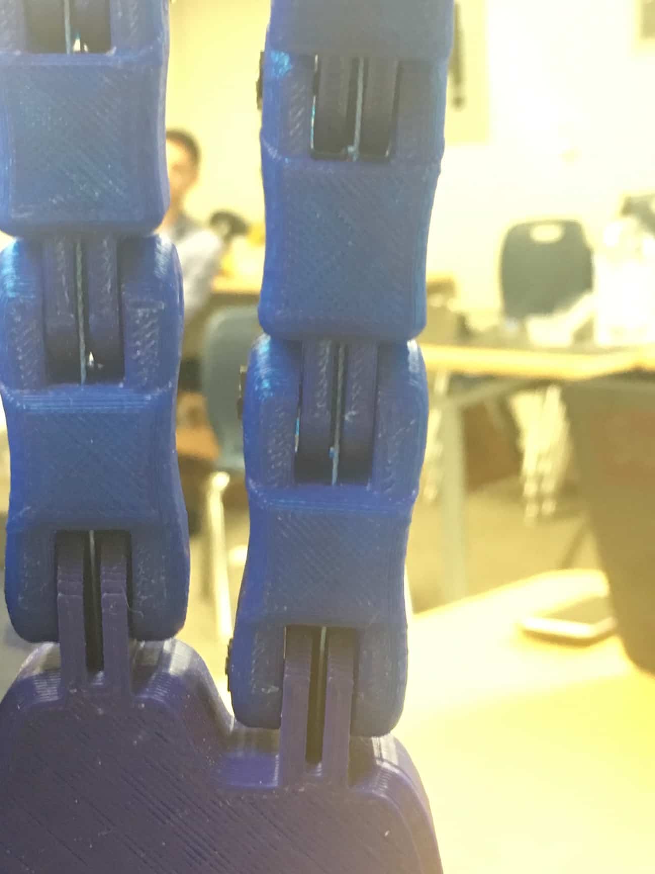
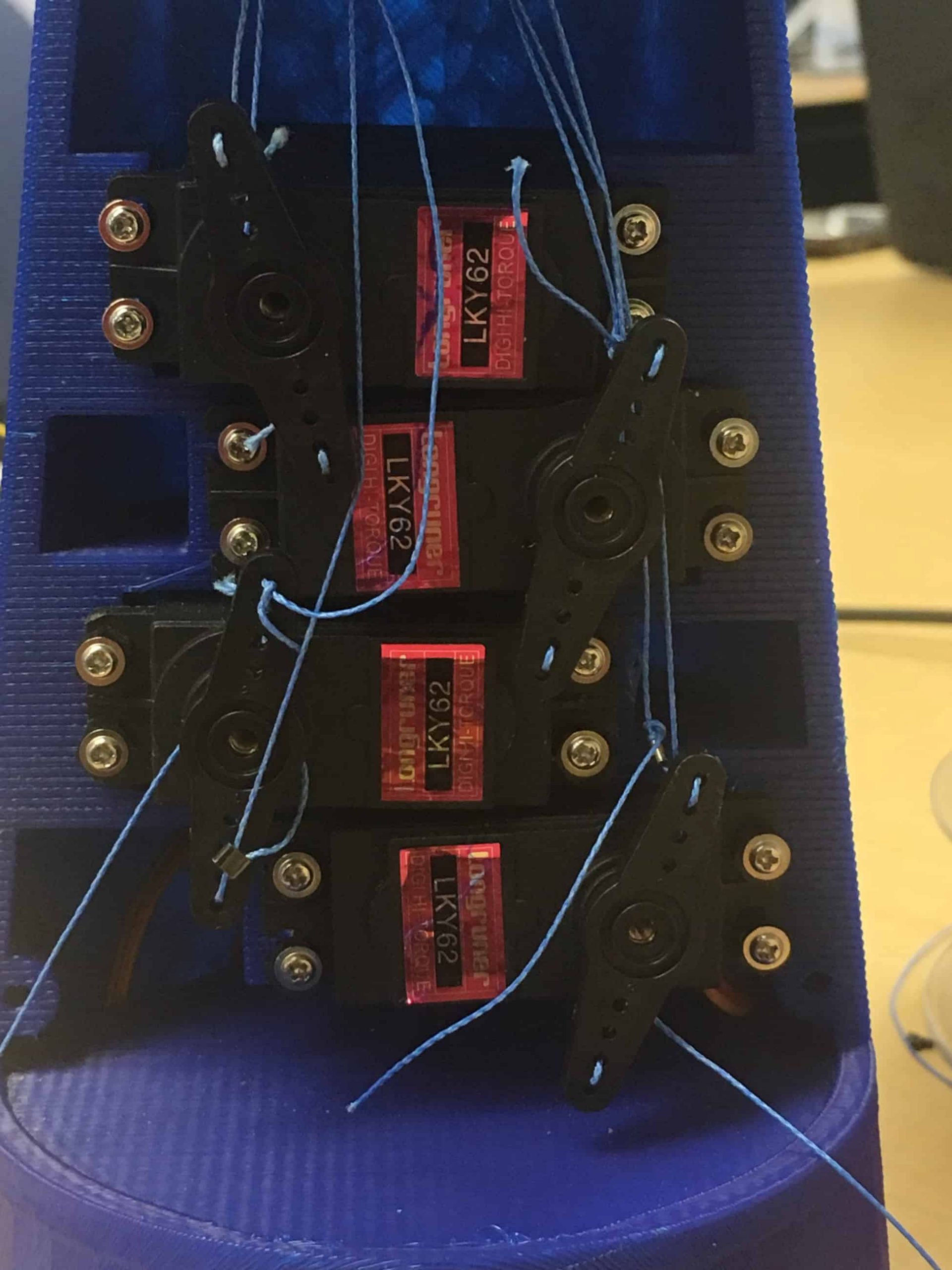
This one week build incorporated many skills other than using mechanical tools. My first step, however, was to use an impact driver(electric screwdriver) to screw in the screws into the nuts, that hold the finger in place. They were Philips-head screws that had unique threading and didn’t have any screwdriver that could match it. That is why I used an impact driver to push it with so much force that it had to fit into the nut. However, that method shreds the thread inside the screw and makes it almost impossible to unscrew. I eventually resorted to using pliers to manually rotate the screws without destroying the screw thread. My next step was to attach two string to a motor each controlling a finger. I designed it so that at any given time one of the strings is taut, while the other loose. When the finger is at its rest position, the string pulling the finger down is taut, while the string pulling the finger up is loose and vice-versa. This pulley-like system allows the finger to have a whole range of motion from its rest position to fully erect. The most tedious part of this process was definitely putting crimps through the strings to hold them in place. After a short period of use, the crimp would slip and let the strings run loose. I solved this by tying tight knots around the crimps holding it in place. Furthermore, each time I tightened a crimp, it couldn’t be undone and I had to use a new crimp each time. 
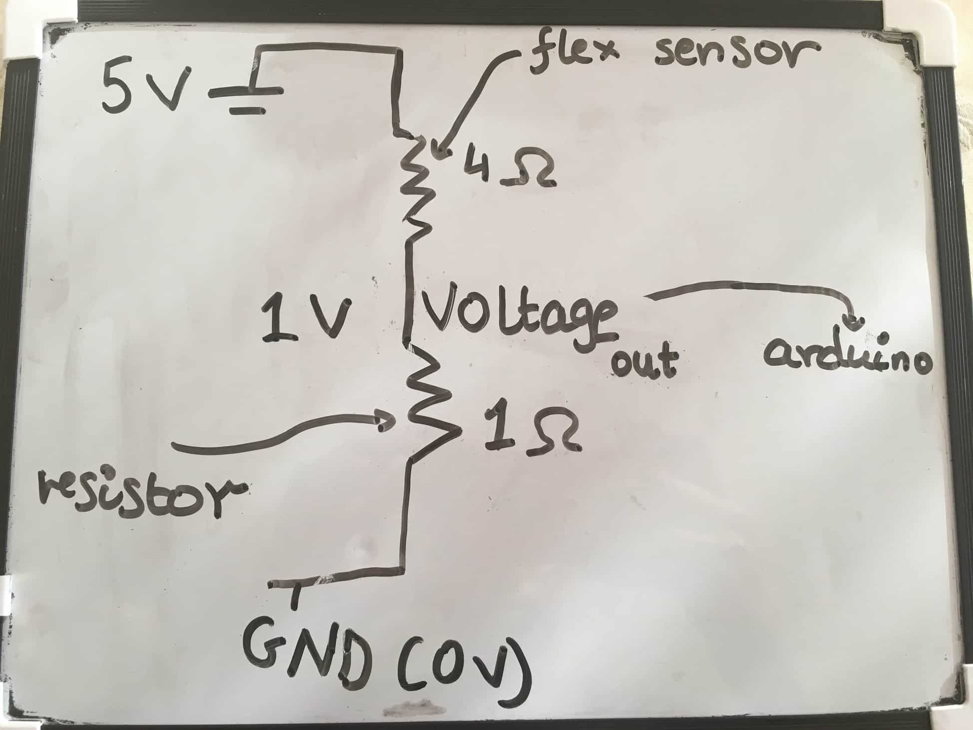
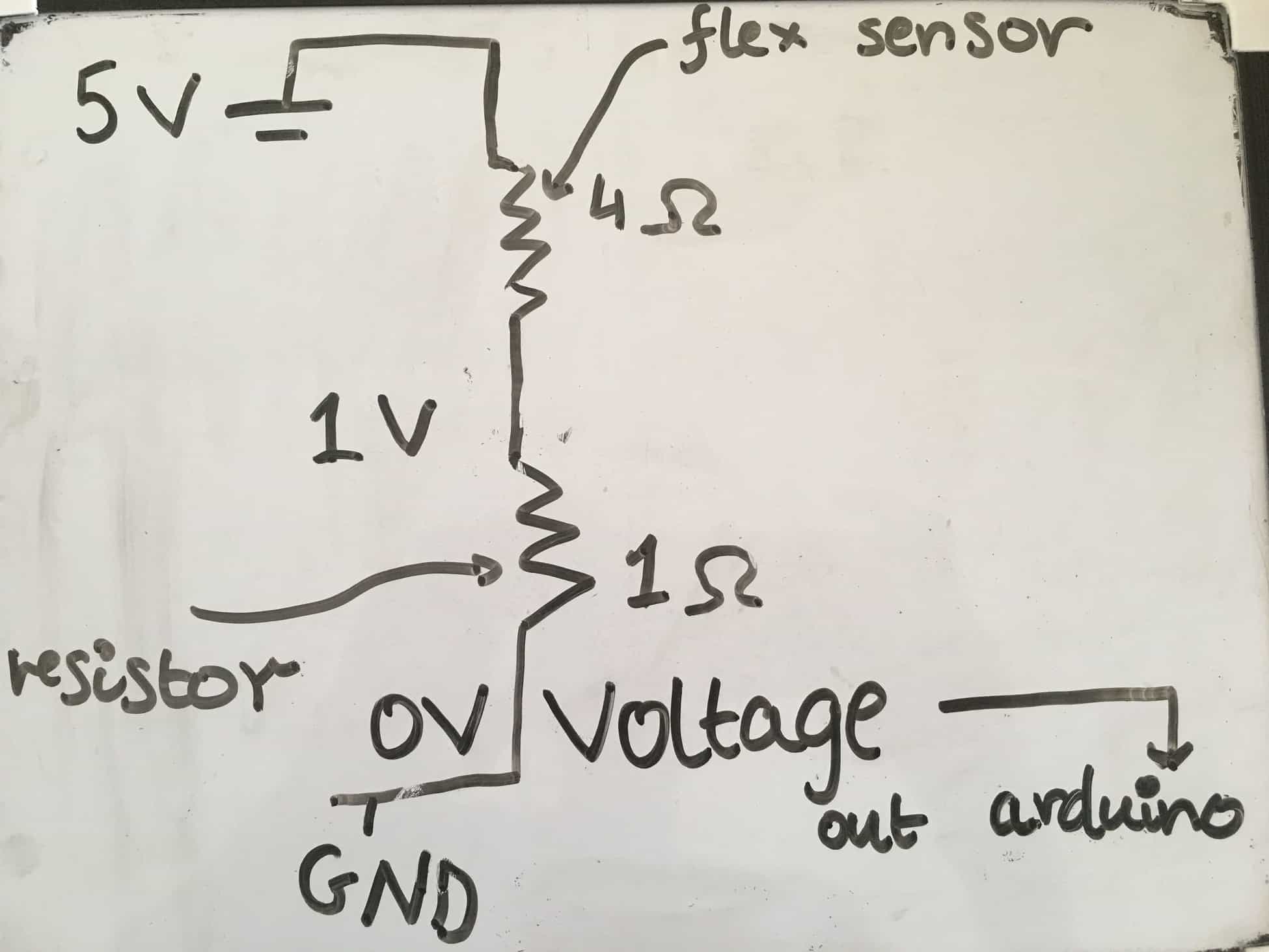
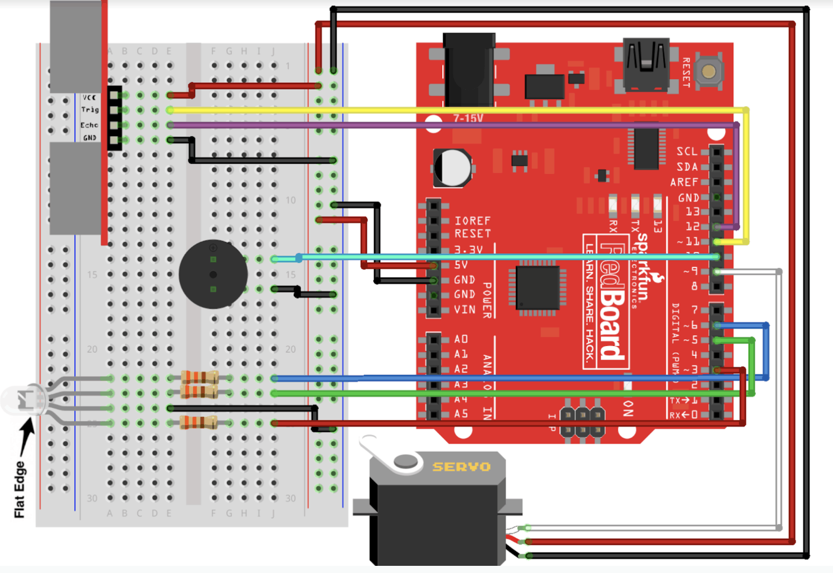
Simultaneous to the build, I transferred all the wiring for my flex sensors to a blank PCB. I had various challenges while trying to solder my electrical components. To create a connection between my ground wire, resistor, and analog wire, I had to solder across 3 joints. I struggled with bridging these joints together in an efficient and clean way. During the first few tries, my PCB would look terribly messy, since I would solder in a clumpy mountain-like fashion. At first, I tried de-soldering the clumpy connections, but I realized that I was burning my PCB since I was overusing my soldering iron. I eventually resorted to using a fresh set PCBs, wires, and resistors. After soldering my flex sensor connections, I began testing the connections of my servos. After a while of testing, my servos stopped rotating. At first, I thought it was a faulty connection, but then I realized my battery wasn’t charged. I then used a multimeter to measure the voltage passed through the servos. I found out that there was no power being passed through the servos and realized that the battery was dead.

FIRST MILESTONE

My first milestone was getting four pairs of flex sensors and servos to work together. As the user bends the flex sensor, the servo starts to rotate.

 The circuit contains four resistors, each that are connected to the flex sensors. The flex sensors act as variable resistors, and as I bend them, the voltage across it increases and the voltage across the second resistor decreases, The analog pins on the Arduino will read this voltage passed across the second resistor. Using the map(), the Arduino will map the voltage to a servo’s position. At the end of my code, the Arduino would write the servo to spin to the desired position.


As of now, I have been using an Arduino, breadboard, wires, flex sensors, resistors, and servos. For the first few weeks, I decided to focus on the electrical components and conduct tests with my code. All my Arduino code has been uploaded to this website. To test out my code, I used a breadboard to prototype my circuit before making any permanent connections on a PCB. 


There were several challenges that I encountered during the completion of my first milestone. My breadboard had a lot of wiring and due to unfortunate circumstances, the supply of jumper wires ran out.  I had to strip solid wire and use that to make my connections. Even though solder wire serves well as a temporary replacement, they don’t tend to last long and often slip out of the breadboard holes. During many occasions, my servos would not rotate, because one of the power wires had popped out of the socket. Moreover, whenever I had to debug, I ended up rewiring my whole circuit since it was very hard to see which wire was malfunctioning among the jungles of wires present. 

STARTER PROJECT – MOTION ACTIVATED ALARM

For my starter project, I decided to build a motion activated alarm using an ultrasonic distance sensor. When a person moves in front of the alarm, the Arduino will beep a buzzer, flash lights on an RGB LED, and rotate a servo.


OUTPUTS


A piezo-electric buzzer functions by containing piezo crystals in between two conductors. When voltage is applied across these crystals, they push one conductor and pull the other conductor. The continuous pull and push action generate a sharp sound wave.

An RGB LED produces a whole variety of colors by combining the three colors(red, green, and blue) in different brightnesses. To adjust the brightness of each color, the Arduino uses PWM signals that assign each pin a certain value.


SENSING


The distance sensor has 4 pins, – VCC, GND, trig, echo. The first two pins manage power. The Vcc manages incoming power, while GND simply serves as a return path for all the current. The trig pin(output) sends a signal, which eventually reaches an object and reflects off it. The echo pin(input) then receives the signal and measures the time taken for the signal to reach the object. The code then multiplies that time by the speed of sound in air, to calculate the distance.

Stay Connected to BlueStamp