Self Monitoring Plant
| Engineer | School | Area of Interest | Grade |
|---|---|---|---|
|
Raimi B. |
Saint Anns High School |
Bioengineering |
Incoming Softmore |
THE FINAL PROJECT! (3RD MILESTONE.)
There are two sections of new code I used for the water pump. The first is a function called demo two it runs the motor up to full speed waits three seconds and then turns it off.
The second piece of code is an if statement that checks if the moisture sensors has the moisture of the plant below 30% – which is the ideal water percentage there should be in the soil. and does demo two if it is.
Hints: I originally had the final piece of code as a while statement rather than an if. This didn’t work because if it was below 30 the pump would keep pumping but never get to checking whether the water sensor had gone above 30. The solution I have is turning the while to an if but you could also just put the sensor reading inside the while statement!
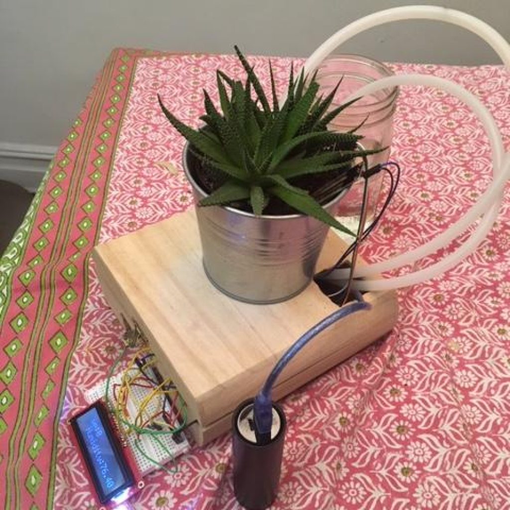
WATER PUMP
MOTOR DRIVER
CODE
WATER PUMP
so the pump itself is actually just a dc motor that is connected to an impeller. Now this impeler’s blades are angled downward so that when the impeller whips around the centrifugal force pushes the water against theses
Tilted blades and off in a streamlined jet out of the end of the tube. As previously said this impeller is powered by a D.C motor and in order to control it with my arduino I needed the motor driver.
MOTOR DRIVER
So a motor driver is basically a voltage amplifier and there are a few reasons it is necessary in order to control a motor, for my project the most important of which being that an arduino just doesn’t give enough power in order to control a 12 volt motor like the one in the pump. The motor driver is able to increase this voltage by having ports that can connect a battery pack to the circuit in addition to the 5v supplied by the arduino. It is made up of 4 mosfets that I like to think of as switches, they are organized in a square around the motor and if two in a diagonal from each other are switched on by the code a current will flow between them and through the motor on a diagonal- therefore making the motor spin. This mosfet motor setup is called a h-bridge and my L298N motor driver is special it actually has two of them- but I only needed one for this project. There are three pins on the motor driver needed to control the pump, the enable A pin is used to enable the current to flow the motor driver so basically the speed of the motor. The input 1 and 2 pins control the mosfets on for the left hand motor, (which is the side I am using.) All these pins connect to my arduino in order to be activated by my code.
CODE
There are two sections of new code I used for the water pump. The first is a function called demo two it runs the motor up to full speed waits three seconds and then turns it off.
The second piece of code is an if statement that checks if the moisture sensors has the moisture of the plant below 30% – which is the ideal water percentage there should be in the soil. and does demo two if it is.
FIRST AND SECOND MILESTONE
What I learned:
When I first started putting together the project I throw every piece onto the breadboard and arduino upload the code, crossed my fingers and just hoped that it would work。 Evidently that jumbled mess of wires and sensors didn’t do a thing and I was essentially at the same place I had been at at the beginning but now just with a big mess in front of me. At this point I took out all the sensors and other unneeded wires and I restarted but this time only with the lcd screen I went through very carefully and connected each wire exactly the way my schematic told me to. Finally after doing this more careful method my screen worked. I did the same method with the other sensors and eventually they all worked. I learned that being precise in such a way from the beginning not only saves time but also confusion and stress. I was also able to implement this lessons when writing my code as I took one sensor at a time and put their information into the combined document individually and into exactly the write place.
Hints:
So when the sensors update on the serial monitor they state their readings on the one line below. However on the LCD display this isn’t possible and when the readings update all the words on the screen jumble and become unreadable. My solution was to create a loop that has the screen clears every time between checks so that the updates are re-written in the same spot each time.
My 1st milestone was getting the sensors and the LCD display to work independently witch turned out to be kind of homogeneous with my second mile stone to get the sensors displaying their information on the LCD so this is kind of san overview of both milestones.
Lcd display
Moisture sensor
Humidity sensor
Lcd display
The lcd display works pretty much like a flat screen T.V. It has a ton of little lights or pixels that turn on and off in order to create the words. I decided to use the LCD display so that I could show the data without having to open up the serial monitor on my computer!
Moisture sensor
The moisture sensor has two probes on it and they are each lined with copper plates now copper is conductive with water so when the probs are put into the moist soil an electrical circuit is completed and current is able to flow between the probes. The more the current is able to flow- the less resistance there is- and the more water there must be in the soil. By this logic if there is more resistance than there must be less moisture in the soil. The sensor is able to take this resistance and convert it into an integer to represent the amount of water – or lack there of- in the soil! This number is on a scale from about 0- no moisture to 1023- a lot of moisture. The arduino takes that number and maps onto a scale of 0 to 100 – basically making a percentage for us to look at- that percentage is then displayed on the lcd display screen.
Humidity sensor
The humidity sensor works in a very similar way to the moisture sensor! Inside of it one will find two plates with a moisture substrate pad between them. The plates are electrodes meaning that they can conduct electricity through/with the moisture. As the humidity rises the moisture substate accumulates more moisture and the current is able to flow. the resistance this current faces is taken in by an IC pin witch is able to translate that hindrance into a number that the microcontroller is able to read. The arduino code puts that number into a float and displays on the LCD display.
STARTER PROJECT
My starter project was the T.V.B.gone- a really cool futuristic gadget that could turn off any tv’s in the surrounding area. Now I can annoy my family and enjoy my newly learned knowledge on how to solder, desolder, and all the electrical components on the kit.
DEMONSTRATION
All TVs and tv remotes communicate through infrared light. Now this pretty crazy,infrared light is all around us the sun emits tons of it how can a remote interact with the tv using IR if there is already all this IR around it in the first place? that seems like trying to hit a dart board with a dart made out of air. Well here’s the answer: the tv has sensors on it now these sensors have been programmed to ignore all surrounding ir except for some important exceptions. You see when engineers are as creating the tv and remote they code in certain IR sequences that the remote can shine at the TVs sensors the TV picks up these specific codes and understands what function to do. So for example if you want to put up the volume then when you press the volume button on the remote is really shining the infrared code for volume at the TVs sensor. The T.v b.gone doesn’t have ir codes for every button on a remote but has the on off codes for a ton of televisions! However it still is unclear how the circuit gives power to these pulsing it led. So let investigate first of all there is micro controller it is basically a small computer that has all the code programmed in it and that code has the pulse times for the leds in it! Next there are 5 transistors 4 of them act as switches for the led that turn them on and off in time with the micro controller’s code. There is one more transistor that communicates with the button and allows any charge enter the transistor led system. The ceramic oscillator acts as a clock and is used to keep the time of the chow fast the current is moving.it is used to sync up the rest of the board with the microcontrollers speed.Finally The 2 Capacitors are energy storers. Meaning that if any other particles such as sound were in the circuit that energy would be taken in by them. And with all those parts working harmoniously the TV.B.Gone is able to operate.
The major lesson I learned during this project was the importance of being diligent. Solder is extremely difficult to undue once it’s solidified around a component and desoldering is made even more difficult with the TV.B.Gone because the wholes are so small! In my haste I didn’t read the instructions carefully enough and ended up soldering the ceramic oscillator into the wrong three holes. The component was extremely hard to get out and once I did all of the legs fell off. I had to get another oscillator from another kit! The holes were still full of solder because they were so small and the whole mess was inconvenient pain and something that could have been easily avoidable if I had been just a little bit more cautious.