Facial Recognition Protected Safebox
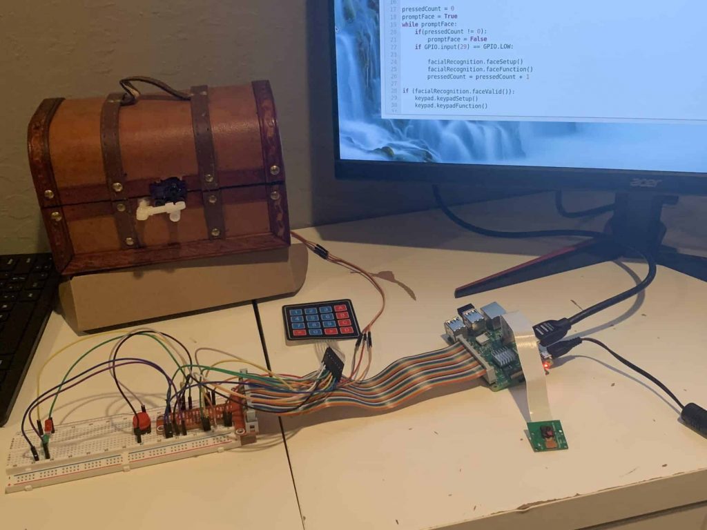
I built a facial recognition model that can predict my face with high confidence and accuracy. Using this as a measure of security, I wanted to make a safe which would be protected with facial recognition and a 4 digit password. The data is processed and interpreted with the Raspberry Pi, which handles the control flow and GPIO’s. When fed a live image capture from the Raspberry Pi camera, my facial recognition detector looks for me and when it sees me with at least 60% confidence(along with the correct password), a micro servo spins an attachment in such a position that the safe becomes unlocked.
| Engineer | School | Area of Interest | Grade |
|---|---|---|---|
|
Rahul N. |
SAINT FRANCIS HIGH SCHOOL |
Computer Science and Electrical Engineering |
Incoming Senior |
FINAL MILESTONE
Prior to this milestone, I had all of my software working. Now, I needed to see if my servo would actually turn. In order to do this, I wrote some servo tester code for 2 functions, “LOCK” and “UNLOCK” by making use of the RPi.GPIO library. I first declared the servo object, then I started the servo using the start command. Then I set a duty value (value between 2 and 12 that corresponds with a degree between 0 and 180). Once I got the servo to run as I wanted it to, I imported that file into my master file to be incorporated in the control flow of my security precautions. The moment of truth was seeing the servo move into the unlocked position after both facial recognition and password measures had been passed.
My next step was using a handsaw to cut out a slot to keep my servo in the front of the box and a divot in the back of the safe for cable management. This was a really long process since my saw was dull, but eventually, I got the micro servo fitting in the slot with a snug fit. Now I had to create the locking mechanism. While brainstorming the mechanism, I realized that if I added attachments onto the servo and onto the safebox that would prevent the safe from opening in the locked position and allow it to be in the unlocked position. I needed to have an obstacle that prevented the servo’s attachment from moving up, hence keeping the safe locked. At the same time, I had to allow the safe to open if prompted to. Once I figured this out I took some PVC parts that I had in my garage and hot glued them to the servo attachment and the safebox in the fashion I had brainstormed. Once letting that dry, I applied a layer of wood glue around the joint to make the attachments’ connections to their respective components stronger.
A day later I tested out my idea to make sure the attachment would be strong enough to keep the safe locked. With that confirmed, I attached everything back to my Raspberry Pi setup and tested out my program. With my project working as I had expected it to, I had completed my final milestone.
REFLECTION
Coming into Bluestamp, I already had a passion for Computer Science and knowledge in the field. However, II had little to no experience with engineering. Through my three weeks at Bluestamp, I developed engineering skills and more importantly a passion for engineering. I still expect to study Computer Science as my major in college, but I have opened the door for engineering in the sense that I will understand what is going on and manifest my ideas into projects with more independence.
					# Servo Unlocking Code
import RPi.GPIO as GPIO
import time

def servoUNLOCK():
# Set GPIO numbering mode
GPIO.setmode(GPIO.BOARD)

# Set pin 11 as an output, and set servo1 as pin 11 as PWM
GPIO.setup(11,GPIO.OUT)
servo1 = GPIO.PWM(11,50) # Note 11 is pin, 50 = 50Hz pulse

#start PWM running, but with value of 0 (pulse off)
servo1.start(12)

# Define variable duty
duty = 12

# Loop for duty values from 2 to 12 (0 to 180 degrees)
while duty <= 2:
servo1.ChangeDutyCycle(duty)
servo1.ChangeDutyCycle(0)
duty = duty - 1

# Turn back to 90 degrees
print ("UNLOCKING")
time.sleep(3)
servo1.ChangeDutyCycle(12)
time.sleep(1.5)

servoUNLOCK()

servoLOCK()
FOURTH MILESTONE
In this milestone, I utilized the GPIO pins to add more functionality to my project. In order to create circuits, I used a ribbon cable to connect a breakout board to the GPIO pins on the Raspberry Pi. Next, I put the breakout board into the breadboard. Now that I had this setup, I started creating circuits. First, I wanted to make it so a button could activate my python script. I connected one side of the button to ground and the other to a GPIO pin. The way that the breadboard works is that all 5 pins in a numbered row are the same. When the button is not pressed, I made it so that the circuit works. When the button is pressed, the circuit breaks. With my code, I made it so that when the circuit breaks, my facialRecognition.py faceFunction() function runs. I utilized the RPi.GPIO library to gain the functionality of the GPIO pins. Another way you can get the functionality is with the gpiozero library. These are modes of Raspberry Pi GPIO.
I also used the GPIO pins to set up my keypad. For my final project, which is a safebox, I wanted to have 2 measures of security. Only when both measures of security are passed will the safe open. The way the keypad works is that it has 4 horizontal wires and 4 vertical wires. Based on the character chosen on the keypad, 2 wires will be different levels than the rest (2 will be high with the other 6 low). I connected the horizontal wires to odd pins with GPIO capability and the vertical wires to even pins with GPIO capability for ease of understanding. Using nested for loops and treating the keypad like a matrix, I was able to take an input key and output the value of that key. With a little manipulation, I set a password and checked to see if the inputs were being put in such an order that the inputs matched the password.
My safe now has 2 layers of security. The first is facial recognition. If that is passed, the user must type in a password into the keypad. If the password is correct, the safe will open. For now, I do not have working Servo motors so I am demonstrating the output and success of my project with LEDs. If all layers of security are passed, a green LED will flash. If something fails, the red LED flashes. Hopefully, the new Servo motors come in tomorrow and I can attach that to my safe. That will be my final milestone as it will show that I have a working facial recognition/password protected safebox.
					#keypad code
import RPi.GPIO as GPIO

def keypadSetup():
    GPIO.setwarnings(False)
    GPIO.setmode(GPIO.BOARD)


#declaring global variable valid to true
valid = True
def keypadFunction():
    global valid
    MATRIX = [ [1,2,3,'A'],[4,5,6,'B'],[7,8,9,'C'],['*',0,'#','D']]

    row =[13,15,33,37]
    col = [12,16,18,40]

    for j in range(4):
        GPIO.setup(col[j], GPIO.OUT)
        GPIO.output(col[j], 1)

    for i in range(4):
        GPIO.setup(row[i], GPIO.IN, pull_up_down = GPIO.PUD_UP)

    checker = 0
    valid = True
    password = '1234'
    print('----')
    while(True):
        if (checker == len(password)):
            break
        for j in range(4):
            GPIO.output(col[j],0)

            for i in range(4):
                if GPIO.input(row[i]) == 0:
                    temp = MATRIX[i][j]
                    print('*', end = '')
                    if (temp != int((password[checker:checker+1]))):
                        valid = False
                    checker = checker + 1
                    while(GPIO.input(row[i]) == 0):
                        pass

            GPIO.output(col[j],1)
    print('')
    print('----')
    if(valid):
        print('keypad access granted')

    else:
        print('keypad access denied')

    #print(valid)
    #GPIO.cleanup()
    #print('cleaned up')
#keypadSetup()
#keypadFunction()

def keypadValid():
    return valid
THIRD MILESTONE
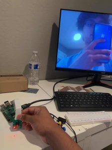
This milestone is pretty similar to my first milestone, yet it is a lot more important when speaking in terms of my project. Knowing how to use the Nanonets model building tool now, I uploaded 200 pictures of myself and 300 pictures of random people and got right into annotating. I assigned each person in all 500 pictures a label of either “rahul” or “unknown”. Once I did this, I trained the model and tested it on my Raspberry Pi with the live image feeding. I was getting spotty results so I decided to troubleshoot it. I quickly realized that the reason for the spotty predictions was the quality of the Raspberry Pi camera. To fix this, I took some images with the Raspberry Pi camera and put them into the Nanonets model. Once I annotated them, I retrained the model and I got really confident and accurate predictions. Now I have a working facial recognition model.
Another big aspect of this milestone was parsing through the response that Nanonets gave. The response could be interpreted as a python dictionary, but it was in text format. To combat this issue, I used json.loads() method function from the JSON library to convert the response into a dictionary. The behavior of this data structure is described in the diagram. Doing this allowed me to return isolated variables (like the label, which measures accuracy, and the score, which measures confidence) that I can use to determine if access to the safe will be granted. My next step is to add a button that runs the script and getting other accessories working via the breadboard.
SECOND MILESTONE
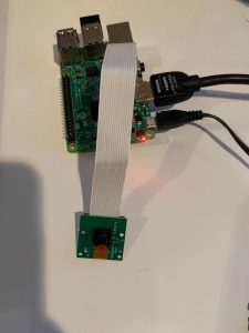
My second milestone was setting up my Raspberry Pi. In order to get the Raspbian operating system onto my raspberry pi, I needed to write it on a micro sd. Once I did that, I inserted the micro sd into the slot on the bottom of the raspberry pi. Afterward, I connected the accessories like the keyboard, mouse, power supply, and monitor. Next, I had to do the basic setup of a Pi, which involves changing the password and checking for software updates. I did this by typing the command “sudo apt-get update.”, into the terminal. After this, I wanted to establish my pi as a VNC server so I could access it from my laptop. This was important because it permitted me to screen capture the code and processes the Pi undergoes for my video. I added the camera to the raspberry pi with a ribbon cable. After enabling the camera in the raspberry pi configuration, I tested the camera for the first time. The next step was feeding a live image of myself from the raspberry pi camera. In order to do this, I implemented this code. I tested out this with my object detection model finished in milestone one and I was surprised that the model still worked with good accuracy and confidence. The next step is to get the facial recognition model built and trained to work with the live image capture from the raspberry pi.
					from picamera import PiCamera
from time import sleep

camera = PiCamera()
camera.vflip = True
camera.start_preview()
sleep(2)
camera.capture('object.jpg')
camera.stop_preview()
FIRST MILESTONE
My first milestone was getting a custom model for object detection trained and tested. When creating my build plan I decided that I wanted to test out image recognition using a pre-trained model before creating a facial recognition model. This allowed me to familiarize myself with TensorFlow and understand what errors I would encounter along the way. While doing this I wanted to familiarize myself with Linux conventionality so I installed WSL (Windows Subsystem for Linux) along with Ubuntu. After getting Linux set up, I installed all of the necessary modules via packages and libraries. {Commands to do this : Sudo apt-get install liblas-dev liblapack-dev python-dev libatlas-base-dev gfortran python-setuptools libjpeg-dev. Sudo pip install Pillow. Sudo apt-get install -y protobuf-compiler. Pip3 install –user tensorflow}. Originally, I was following a tutorial for image recognition. The following were some of the issues that I encountered. A need to access a previous commit from Github’s TensorFlow repository which I solved by using git checkout . Accessing Linux files on windows and vice versa which I solved by creating an alias via the command line, allowing me to access my computer files on Ubuntu and Bash. Making classification code compatible with TensorFlow 2 which I solved by editing the classification code I used with a simple command “import tensorflow.compat.v1 as tf”
I kept hearing about the term “object detection”. I was curious to find out what the difference between the two was and I realized that object detection was a more accurate way to facial recognition. With facial recognition being my end goal, I decided to make the switch over to object detection. With this in mind, I was ready to practice training a model. To do this I downloaded 100-150 images of dogs, cats, and cars each and uploaded them to Nanonets. I annotated them under their respective labels and once I finished that process, I trained the model. When I tested the model, I was really surprised by the results. I was getting 90%+ certainty from the model when feeding it images of various cars, cats, and dogs. When I ran the script in bash, I felt accomplished since I successfully had trained a machine learning model for object detection. Completing this milestone was important because I now am familiar with TensorFlow, Nanonets, and Linux. My next milestone is getting a facial recognition model trained and running the script on the Raspberry Pi.