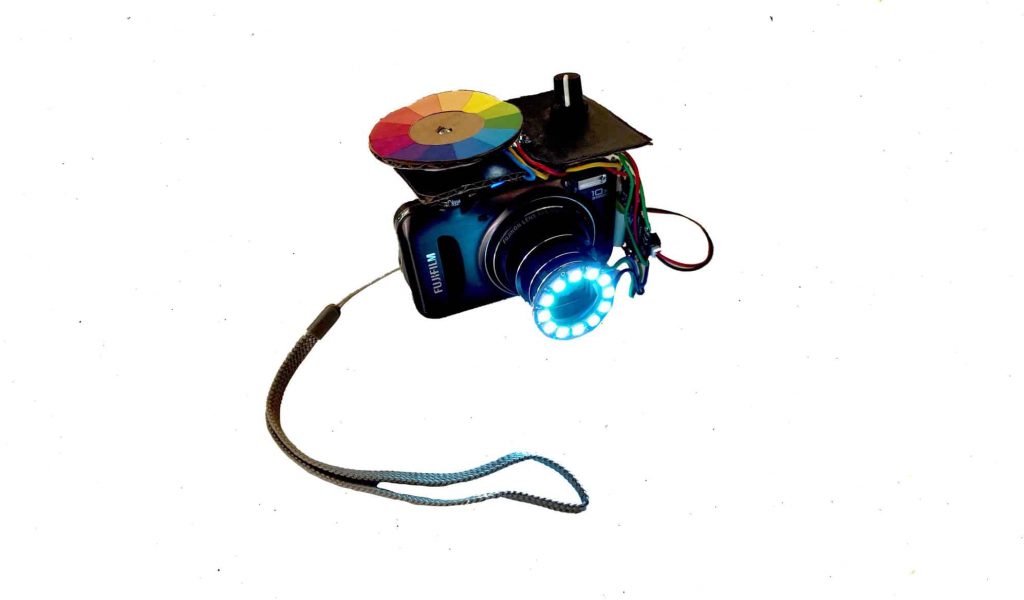
For my intensive project, I created a color spinner camera ring light. Essentially, a ring of led lights changes color when spinning the color wheel. The sensor allows the user to pick a custom color as a color tint filter to photos taken with the camera.
Engineer
School
Area of Interest
Grade
Niharika M.
Redwood High School
Electrical Engineering/ Computer Science/ Data Science
My First Milestone was to create the electronic chameleon itself using the Arduino. This main project forms the basis of my extensions/modifications. Essentially, my project has a few components consisting of the Arduino, the breadboard, and the sensor. Any color held to the RGB TCS34725 sensor is read, and through the use of several other electrical components, the Arduino is able to read the color. This allows for the LED ring to illuminate. I faced issues with the code but I was able to quickly realize my errors and successfully change my code. For my next milestone, I hope to swiftly transition from the Arduino board to the Adafruit Flora.
SECOND MILESTONE
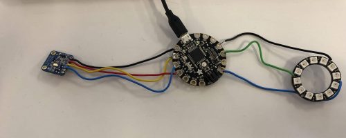
For my second milestone, I transitioned from the Arduino to the Adafruit Flora. I did face some challenges when rewriting the code, but I was able to research online and find solutions, while also learning about new code. I also added a potentiometer to adjust the brightness. I got to learn new code while coding for the potentiometer and I also enhanced my concepts of electrical engineering as I learned how the potentiometer works internally.
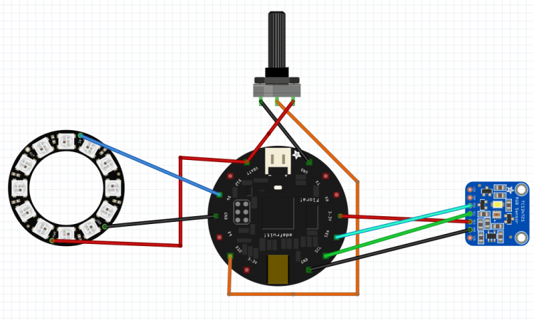
CIRCUIT DIAGRAM
THIRD MILESTONE
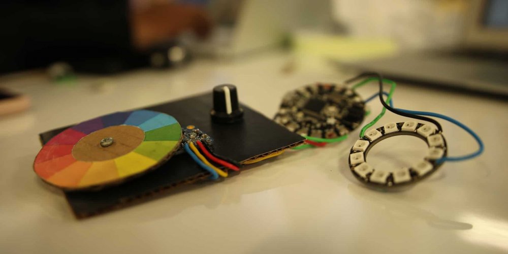
For my third milestone, I physically assembled the project to the camera and I cleaned up the style with a potentiometer knob. I like that the use of my product is custom to the user.I am excited to continue doing projects like this in the future and to expand on my engineering concepts. I did face some challenges when making this project but I think that working to fix them and overcoming them helped me to stay motivated throughout the project and successfully complete it.
MOTION ALARM
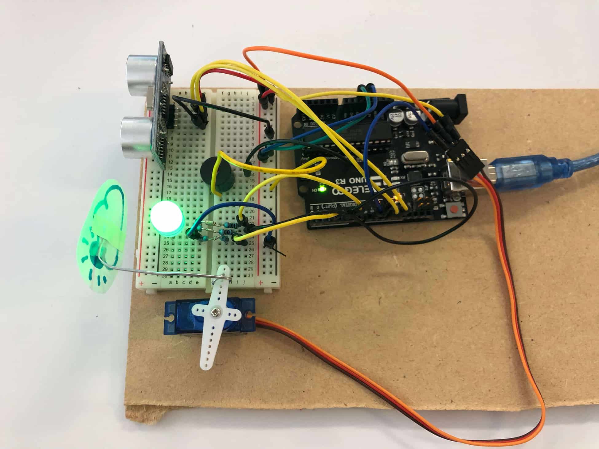
This project incorporated both coding and physical assembly, allowing me to develop both these skills. The Motion Alarm uses a breadboard, an Arduino, and the IDE for Arduino. A servo motor, an LED, and a buzzer all function together both visually and through sound to constitute the alarm. I learned how to solder and gained a better understanding of the electrical components that make up a circuit and the role that each component serves.
HOW IT WORKS
Firstly, the Arduino board is connected to a computer via a USB, where it connects with the Arduino development environment, IDE. I uploaded the code to the microcontroller which executes the code, interacting with inputs and outputs such as the sensors, motors, and lights which make up my alarm. Essentially, the Arduino is capable of taking these inputs (such as the a reading from a sensor from movement) and interpreting that information to control various outputs (like blinking an LED light or spinning of the motor or the initiation of the buzzer sound). The digital pins are the digital inputs and outputs of the Arduino. These are what I connect to the LEDs and sensors to interface the Arduino with other pieces of hardware.
My Motion Alarm works by sensing a motion. The distance sensor determines the distance that this object is. The distance sensor is able to calculate distance using the trigger pin and echo pin. The trigger pin emits an ultrasonic pulse and the echo pin measures the time for the pulse to bounce back and hit the sensor. This time is used to figure out the distance.This distance determines the color of the LED so it light up blue within 10 inches and lights up yellow between 10 and 20 inches, and lastly, green when beyond 20 inches. When the light is blue, the motion of the distance sensor triggers the servo motor which moves in front of the light.
One challenge I faced was that I didn’t have a 330 ohm resistor. To overcome this, I connected two resistors in series to form a 320 ohm resistor. I learned about polarity and that electricity can only flow in one direction through certain electrical components like an LED. I also learned to solder, allowing for more efficient circuit building. This project also reinforced my knowledge of Ohm’s Law.
STAY CONNECTED TO BLUESTAMP
The BlueStamp Engineering Website is set to allow the use of cookies. Cookies help us to give you the best experience on our website. By clicking Accept or continuing to use the site, you agree to use our cookies. If you decline we will not track your information but your browsing experience might be limited. For more information on our Privacy Policy click here.ACCEPTDECLINE