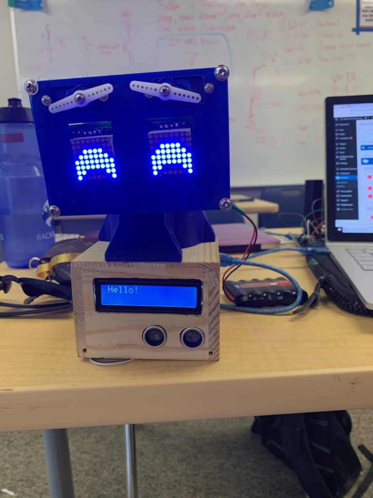
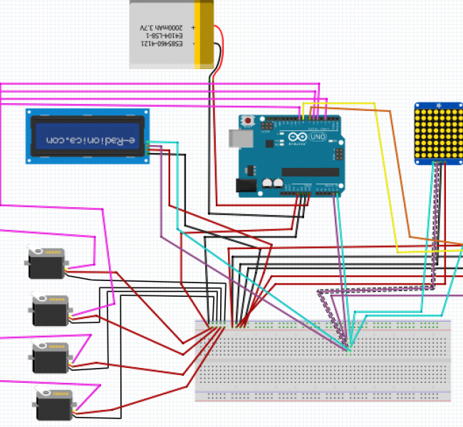
For the first milestone of my Wall-E Emotive robot, my goal was to successfully program two of the Arduino components used in my project and then program them to interact with one another. The components I chose were the 8×8 LED matrix, which would eventually be used to display the robot’s eyes, and the Ultrasonic Sensor, which would allow the robot to determine how far away an object is.
The 8×8 LED Matrix works by running an 8×8 grid of LED dots that are connected to a total of 16 pins. This means each LED dot is positioned at the intersection of two pins.  When a positive charge runs through one wire and a negative through the other, it completes the circuit and causes the specific dot to light up. This can be controlled through simple on/off commands. However, because every row and column share their wires with 7 other intersections, it is impossible to have more than a few lights on without causing unwanted lights to be on. This issue can be resolved by passing the display as an array, rather than a static image. This means that only one row of lights will turn on at a time, but the matrix will run through each row so quickly that to a human, it looks like there is one continuous image being displayed.
The other appliance I have working so far is my ultrasonic sensor. This appliance had two sensors attached that look like mini speakers: one is for output and the other is for input. Essentially, the output sensor emits a sound wave signal that will then bounce off of any object in front of the sensor that is within range. When the waves bounce of the object, the wave signal bounces back sensor and is detected by the input. While this is happening, the computer is timing how long it takes for the signal to go and come back. It then takes this increment of time and multiplies it by the speed of sound, computing the total distance that the signal travelled. This distance in then divided by two in order to determine how far away the object itself is.
For my milestone, I programmed the LED matrix to display a frowny face, but to flip to a happy face if the ultrasonic sensor detects an object within 10 cm of the sensor (this number is arbitrary and can easily be adjusted as desired). In order to do that, I had to set up each appliance to interact with one another, which I did by setting up an if-else statement where the LED matrix responds in different ways depending on the results of the ultrasonic sensor.
One challenge I faced in this process was getting acquainted with all the components. I had never worked with any of the appliances or an Arduino before, and I had never worked with C or C++. Some of the challenges this presented included not having the natural intuition for these components: for example, I didn’t realize I needed to put a backpack on my LED in order to properly connect it to my Arduino. I also didn’t realize that for my conditional statement I needed both an “if” and an “else” (ie “if this happens, then do that, or else do this other thing”). At first, I was trying to program my LED where there was only a function that defined what would happen if the sensor detected an object within the set distance. Soon, I realized I needed a complementary function that would define what the LED should do in the absence of an object.
