Auto-Balancing Segway
The Auto-Balancing Segway is able to keep itself upright at all times, even when the robot is manually pushed
| Engineer | School | Area of Interest | Grade |
|---|---|---|---|
|
Leo S. |
Lynbrook High School |
Mechanical Engineering |
Rising Senior |
FINAL MILESTONE
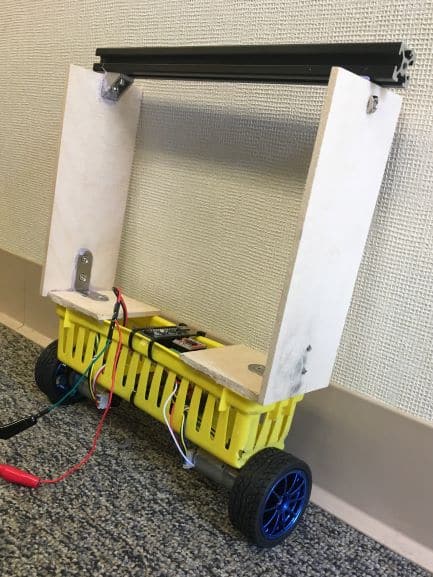
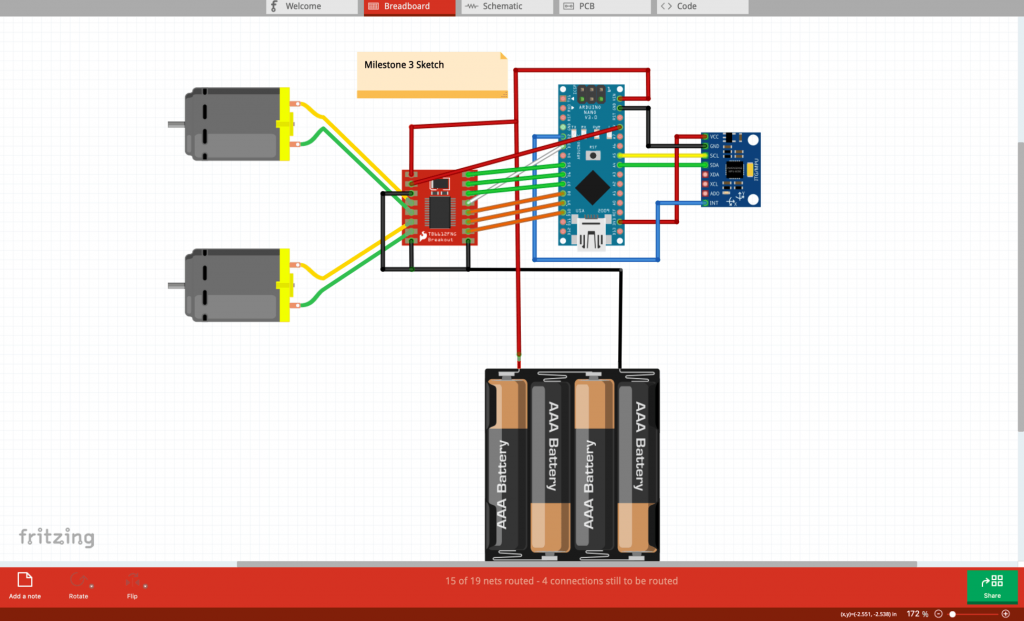
My Third Milestone is the completed segway, which uses an Arduino microcontroller , a gyroscope, an accelerometer, motor driver, and two dc motors. My Arduino will receive values based on information gathered by my accelerometer and gyroscope. It will then transmit that data to my motor driver and the driver will then turn the motors to compensate for any over correction. For my arduino libraries, I used the I2C Library, which is a communication protocol for arduino and I used the MPU6050 library, which is for the gyroscope and accelerometer. The reason why I built the wood and metal on the top to elevate the center of gravity so that the robot will fall less, causing the motors to spin less sporadically. The most challenging Part of my project was soldering all the components together. After filming my first milestone, my instructor gave me a new, smaller motor driver and told me to use it instead. While putting the components together, I decided to solder the system onto a perf board. However, on my first attempt, after I soldered everything together, I accidentally short circuited the connections in the motor driver. Then, on my second attempt, I put the battery in arduino the wrong way, causing it to smoke up and fry itself. Later, on my third try, I found that the gyro/accelerometer had fried itself on the first attempt. After failing three times, my soldering skills became much faster and cleaner, and on the fourth try, I finally got everything working. However, later on, I learned that everyone was having problems with the motor driver and motors I was using, so I switched to new motors and bigger wheels. Overall, I was happy about finishing the project. Originally I was close to being done at the end of the first week, and I was well on the way to finish before the third week. However, after experiencing countless failures, I came close to no finishing in time. BlueStamp has taught me to have patience when facing problems. That its okay to make mistakes, I just have to learn from them.
SECOND MILESTONE
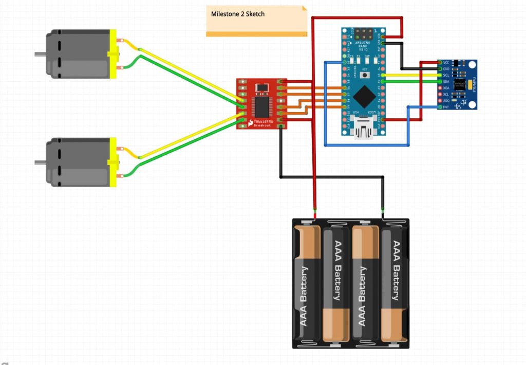
My Second milestone was to switch the L298n Motor Driver to the smaller, solderable MX1508 motor, as well as solder together the Arduino Nano, MPU, and MX1508 together into one circuit board. The reason I needed to use the motor driver was because the Arduino by itself cannot supply enough power into the two dc motors. Another reason I needed the motor driver was because in order to make the motors turn in one direction, and then turn in another direction, I needed to reverse the current going through the two pins on each motor, which can’t be done with an Arduino unless I manually switch the cables connecting the motor pins every time I want to switch directions. Some problems I faced when working towards my second milestone was the switch of motor drivers. Originally, my motor driver wasn’t soldered onto anything, so while the wires were unstable and constantly fell off, the system wasn’t going to short circuit. After filming my first milestone, my Instructor suggested that I solder everything onto one board to make things compact and cleaner. However, once I soldered everything together, my motor driver stopped working, most likely due to a bad connection that caused the driver to short circuit. Unable to desolder any of the parts off the board, I restarted with new parts. After frying both the Arduino and the motor driver, on my third try I was able to get the motor driver working on a breadboard. Once soldering everything back onto a new circuit board, I was finally able to get everything working. However, when testing, I had accidentally flipped the direction in one of motors, making one to go forwards, and one to go backwards, causing the inside of one of my wires to tear, breaking the connection. I was able to fix this by cutting of the defective wire and replacing it with a new one. This entire process of short circuits, torn wiring, and restarting caused my progress to halt for almost two weeks. After this endeavor, I learned that having better, cleaner soldering leads to having a lower chance of short circuiting.
FIRST MILESTONE
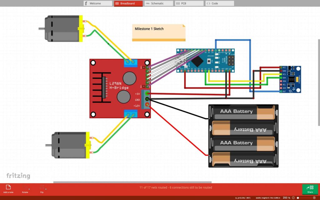
My first milestone was to get both the motors spinning, as well as get the arduino to communicate with the gyrometer/accelerometer. This was extremely difficult because I needed the two DC motors to connect to the H-bridge, and also have the arduino connect to both the bridge and MPU. This system works by having the MPU record data based on how far off the built in gyroscope is from the settings that I inputted. If the readings don’t match my input, then either one or both of the motors will turn in a direction. The H-bridge allows for both motors to be controlled together. One major obstacle I faced while working on my project was the looseness of the cables. While I was testing the system without circuit board, the wires were fine because they were able to be plugged all the way into the metal ends of the arduino and MPU. However, when I soldered the arduino and mpu into the circuit board, the board took up about ¼ th of the wire space, causing the female ends of the cables to have less space to hold onto the main components. After the soldering, I had to deal with multiple instances of either the wires falling off the arduino/mpu, or the system short circuiting. I fixed this by taping electrical tape around the plastic sections of the wires, as well as taping the wires to the main board. Another obstacle I faced were the screw terminals. As I was looking through the system schematics, I saw that I needed to have a common ground, which were all supposed to be connected to one screw terminal. Due to needing to shove three ground wires into one screw terminal, the top screw was always slightly loose, causing the ground wires to come off. I was able to overcome this obstacle by taping all the ground wires together.
MOTION DETECTOR
My Starter Project was the Motion detector. For this project, I used an arduino uno, a piezo buzzer, a RGB Light, a servo motor, and a motion detector. The detector is an ultra sonic emitter. It shoots out a wave from one hole, and then receives the wave from the other hole. Then, by using the formula Distance = time * a sound constant, the motion detector is able to send a value to the arduino. After that, the arduino will then send a signal to the RGB light, the servo motor, and the piezo buzzer based on the value it receives. If the distance is from 0 to 20 cm, then the arduino will send three different values to the RGB light, each representing Red, Green, or Blue and the arduino will also send a signal to the piezo buzzer to vibrate at a certain wavelength to emit sound, then it will send a signal to the servo motor to rotate 45 degrees. If the distance is from 20 to 35 cm, then the RGB light will turn yellow, and from 35 and onwards, the light will turn green.