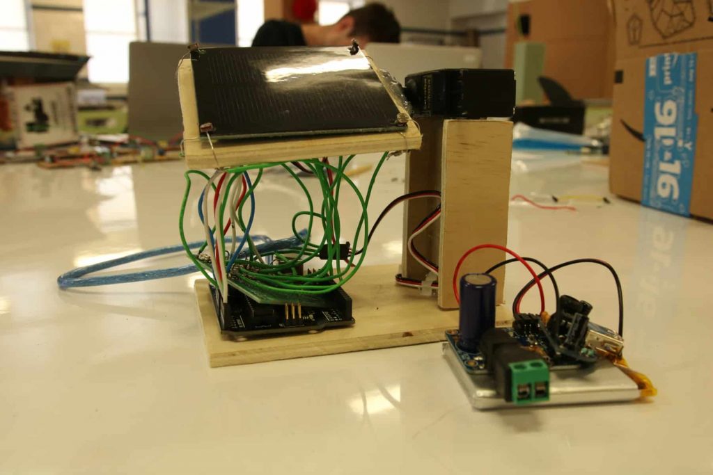
The Solar Powered Sun Tracker uses photoresistors to track the intensity of the sun. With a servo, it is able to move the solar panel to optimize the amount of energy absorbed. In addition, the Sun Tracker can charge a phone.
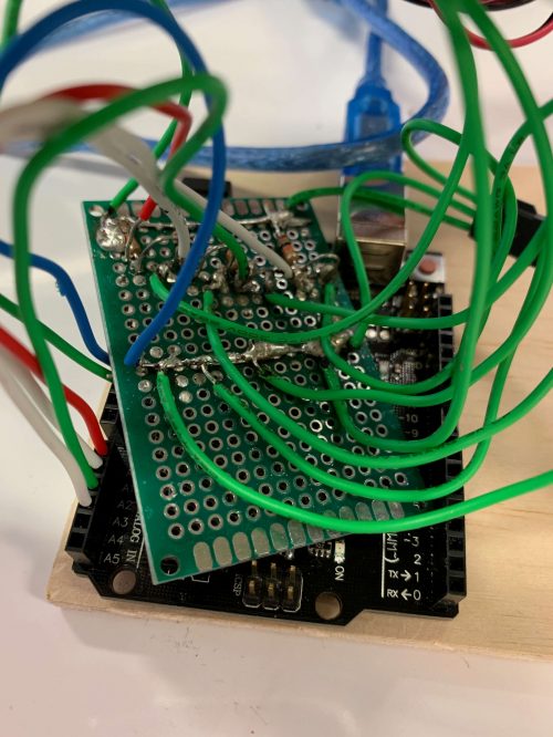
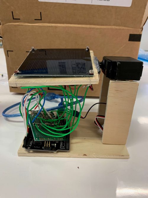
For my final milestone, I built a stand to put all the pieces together and finalized my project. I began by transferring all the wires and resistors from the breadboard to a perf board. A perf board is a small sheet with pre-drilled holes at equal intervals. The board allows for everything to be kept in a more confined area and with it, the photoresistors are able to be separated with wires. Next, I sketched out my plan for the stand and the dimensions. Through the course of this milestone, I learned to safely and efficiently saw wood to obtain my desired pieces. To connect the wood, the servo, and the solar panel, I used hot glue. The greatest challenge I faced was soldering wires to the perf board because it has such a small surface area. Lastly, I decided to have the components of my charger to be a separate part of my project that can be connected to the solar panel when needed. My favorite part of my project was seeing all of my code and physical parts come together at the end.
SECOND MILESTONE
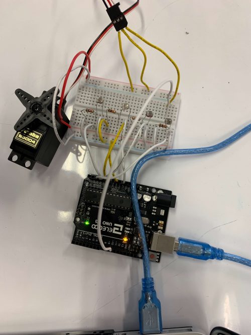
In my second milestone, I wrote code to move the servo depending on how much light the photoresistors sensed. Photoresistors are light-sensitive resistors. When the intensity of light increases, the flow of electric current through the photoresistor also increases. On the other hand, servos are motors that can rotate to a precise angle or a desired position. I connected four photoresistors and the servo to an Arduino. The photoresistors detect any surrounding light and output numbers into the computer based on how bright the light is. I programmed it so the computer will take the averages of two photoresistors and the servo will move one degree to whichever side has the higher number. This process is helpful for my project because I can use it to determine where the sun is the strongest. For my final milestone, I will work to connect the servo to the solar panel so it can optimize the amount of sun it absorbs. A challenge that arose when working on this milestone was I have never used an Arduino before. I had to look at various diagrams to figure out how to connect all the pieces together. Furthermore, I did a lot of research and required a lot of help to program everything.
FIRST MILESTONE
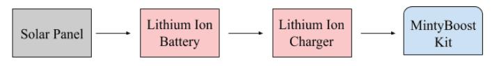
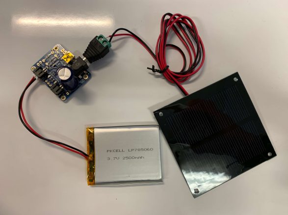
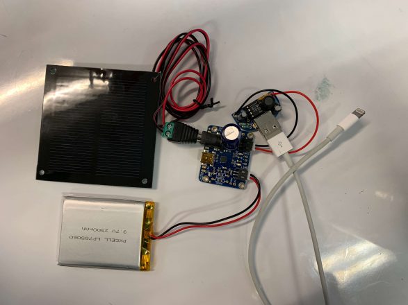
For my first milestone, I connected the solar panel, lithium ion charger, lithium ion battery, and MintyBoost. In order for my project to work, the solar panel absorbs energy and provides it to the lithium ion battery. The battery then transfers electricity to the lithium ion charger. The capacitor will ensure a constant voltage entering the system. Lastly, the MintyBooster will convert the 3v to 5v to charge a phone. A challenge I encountered was my solar panel initially had alligator clips at the ends of its wires; there was no direct way to connect the solar panel clips to the lithium ion charger. To overcome this problem, I clipped off the alligator clips and stripped part of the wires off. Next, I found a barrel jack adaptor and used a screwdriver to securely connect the wires. Hopefully, when I test the charger later, the connection to the solar panel will be successful.
FLOWCHART OF ENERGY FLOW
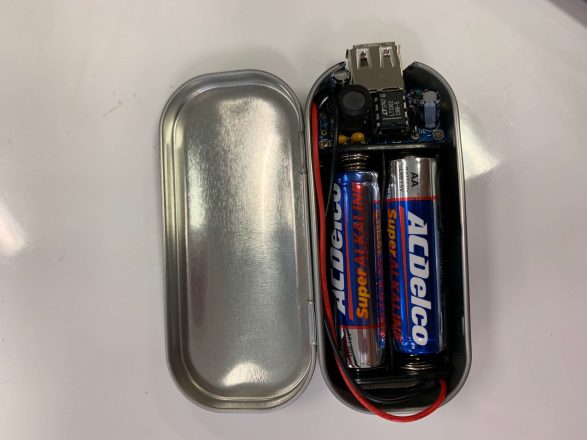
MINTYBOOST STARTER PROJECT
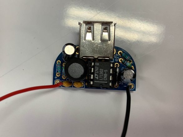
My starter project was the MintyBoost phone charger. The kit converts the 3v provided by two AA batteries to 5v which is suitable for charging a phone. I soldered capacitors and resistors onto the MintyBoost circuit. Resistors are present to control and limit the current flow. Furthermore, capacitors use an electric field to store energy and create smooth input and output voltages. Similarly to the capacitors, I also soldered on a power inductor. Power inductors, however, use a magnetic field instead. Lastly, I used a diode to ensure the flow of the current was in one direction only. With a USB port on the circuit, I could connect the MintyBoost to any charger. When assembling this project, I became more skilled at precisely soldering a wire to the circuit board.
STAY CONNECTED TO BLUESTAMP
The BlueStamp Engineering Website is set to allow the use of cookies. Cookies help us to give you the best experience on our website. By clicking Accept or continuing to use the site, you agree to use our cookies. If you decline we will not track your information but your browsing experience might be limited. For more information on our Privacy Policy click here.ACCEPTDECLINE