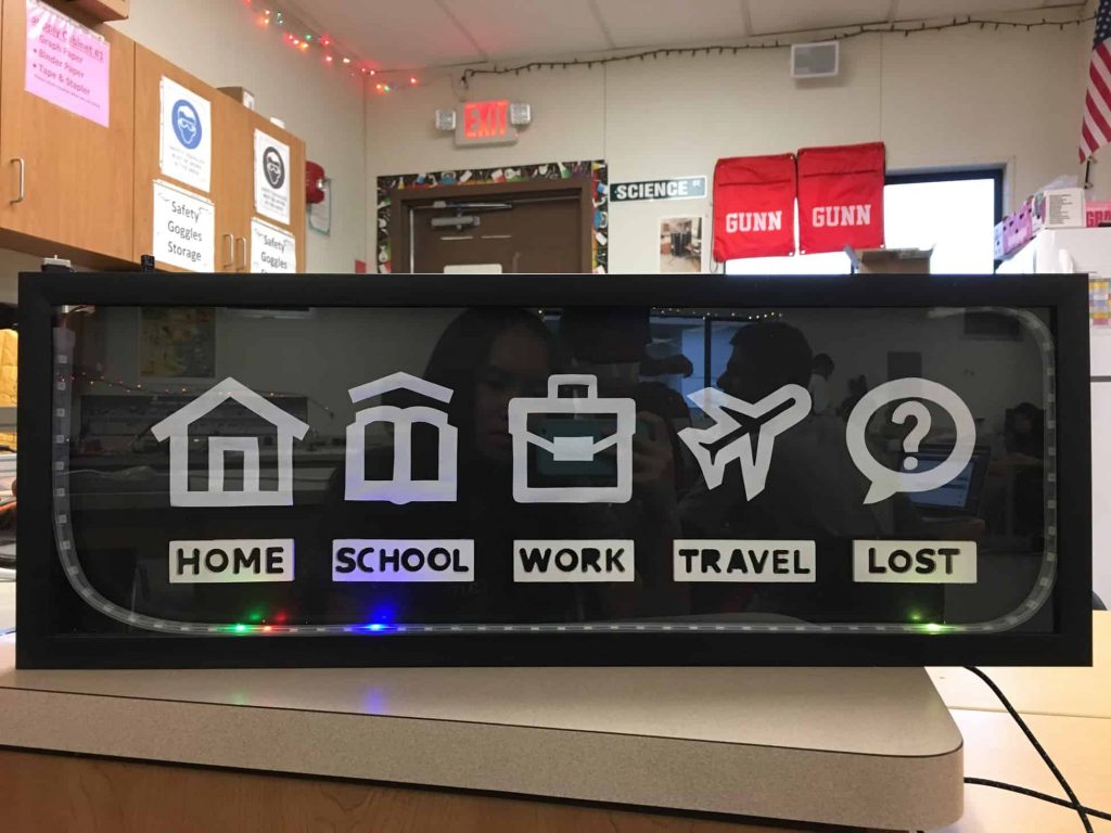
IoT Location Sensing Frame
This frame uses a Particle Photon to control the colors of an LED strip, which changes based on each family member’s location. Complete with an OLED display and an LCD on the backside that displays day of the week, date, time, and temperature.
| Engineer | School | Area of Interest | Grade |
|---|---|---|---|
|
Jennifer J. |
Monta Vista High School |
UI/UX, Computer Engineering |
Rising Senior |
FINAL MILESTONE
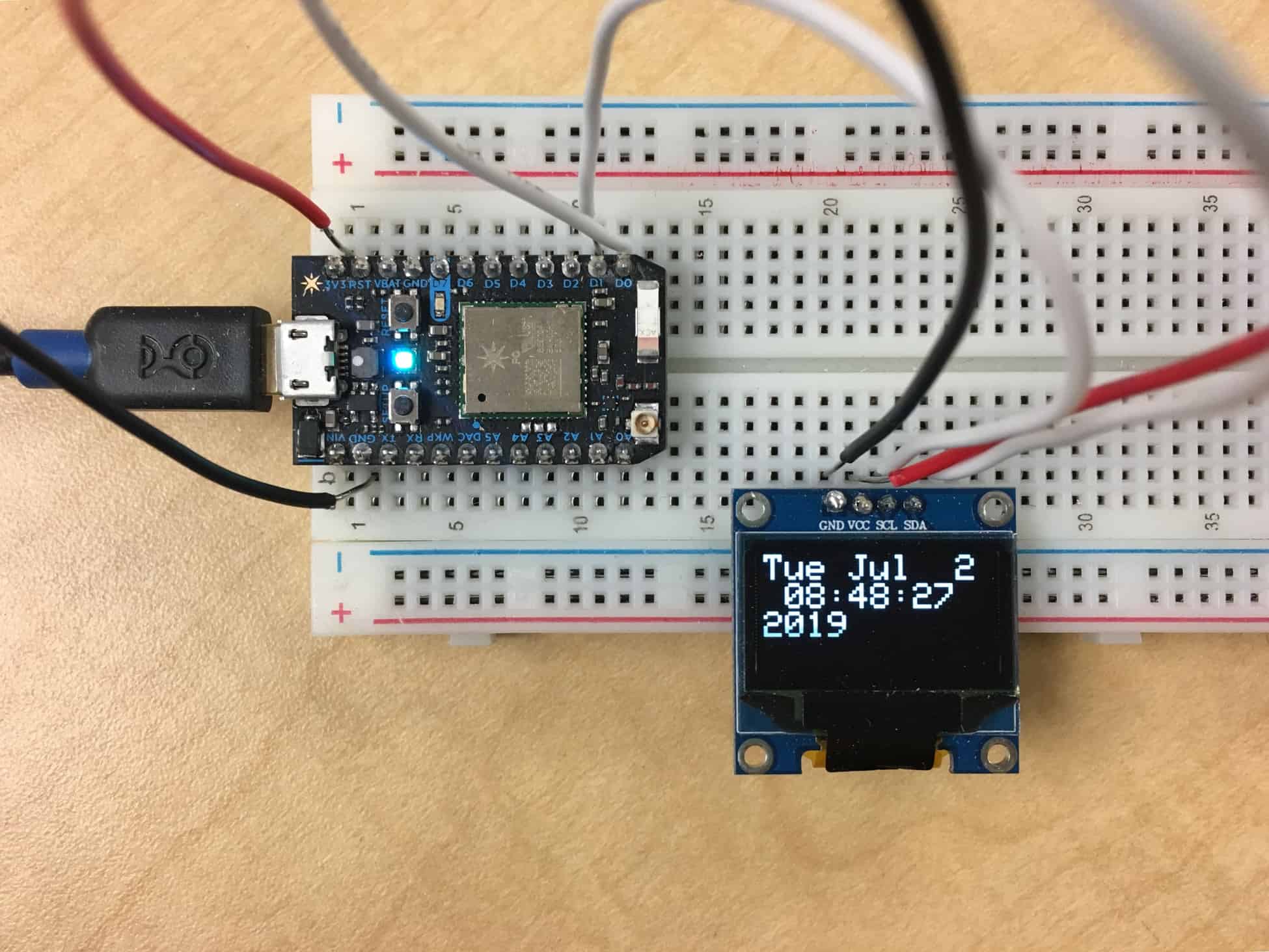
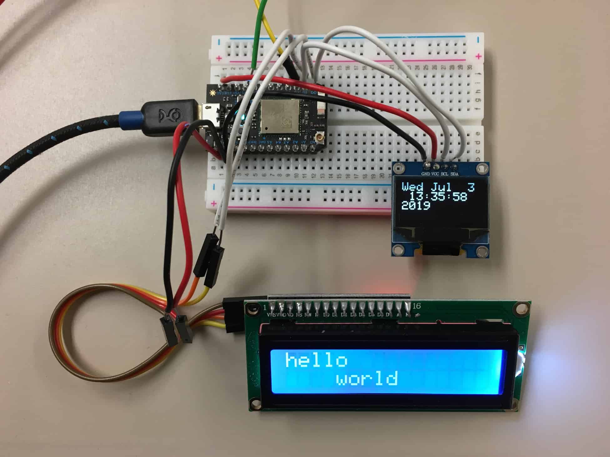
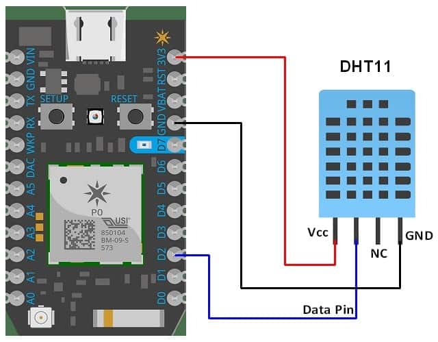
I added a 0.96” OLED display, which stands for organic light-emitting diode, that displays the day of the week, date, and exact time down to the second. OLEDs are very similar to LEDs, however, OLEDs can be easier to manipulate since they can be made to be very thin and flexible. Additionally, OLEDs can act as individual pixels that are self illuminating, meaning that when an OLED pixel is turned off, there is a sharper contrast between the turned off pixel and the remaining pixels that are still on. The OLED display I used has four inputs, ground, power, SCL, and SDA. SCL is the clock line and SDA is the data line. If I were to disconnect the wire that currently connects the SCL pin on the display to the D1 pin on the Particle, then the time on the display would simply stop and would not update in real time. In the Particle Web IDE, I had to code the message that would appear on the display by setting a text color, text size, cursor, and time zone. The message is formatted using the c_str() function in C++. I later added an LCD, also known as a liquid crystal display, that displays the inside temperature in both Celsius and Fahrenheit. Because of how the Particle Photon communicates with I2C devices, I had to also connect the SDA and SCL pins on the LCD to the D0 and D1 pins on the Particle respectively. To get the values for the inside temperature, I used a DHT11 temperature and humidity sensor.
One problem I encountered was connecting both the OLED display and LCD to the Particle. I originally tried setting the digital input pins to be unique for each of the displays, however, when I tested it, only one of the messages showed up on one display and not the other. The problem I had was that I originally thought that the Particle required use of different digital pins for individual I2C devices, but I eventually realized that the Photon actually uses the same pins to send data to multiple devices. After some research on how the Particle communicates with I2C devices, I finally understood how to wire the two displays correctly by using the same pins to send information to multiple devices, and present the exact information I wanted. I also struggled with getting the DHT11 sensor to work, and am still working to get it to display the correct values in the serial monitor. Regardless of the setting I was in, the sensor was unable to produce a humidity value, and the temperature continued to stay at an unreasonable high of 255ºC or 491ºF. I added a 10kΩ pull up resistor between the data and power pin, and even tried switching the DHT11 sensor for a new one, however, the values that were read from the sensor stayed exactly the same, indicating that there was something wrong with either my wiring or my code.
I learned how to display real time information on the OLED display snd connect two different displays to the same Particle.
In the future I hope to figure out the DHT11 sensor and get the correct values displayed on the LCD. I also hope to apply the knowledge I learned at Bluestamp to complete other projects on my own time.
THIRD MILESTONE
My third milestone was simply completing the rest of my project, which includes assembly of the frame, cutting out and painting my location icons and labels, and securing the various components in place.
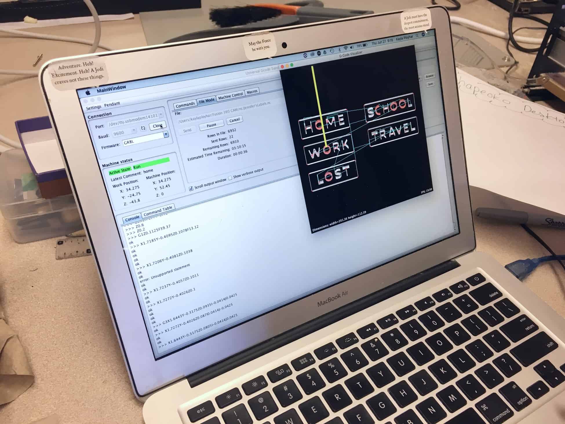
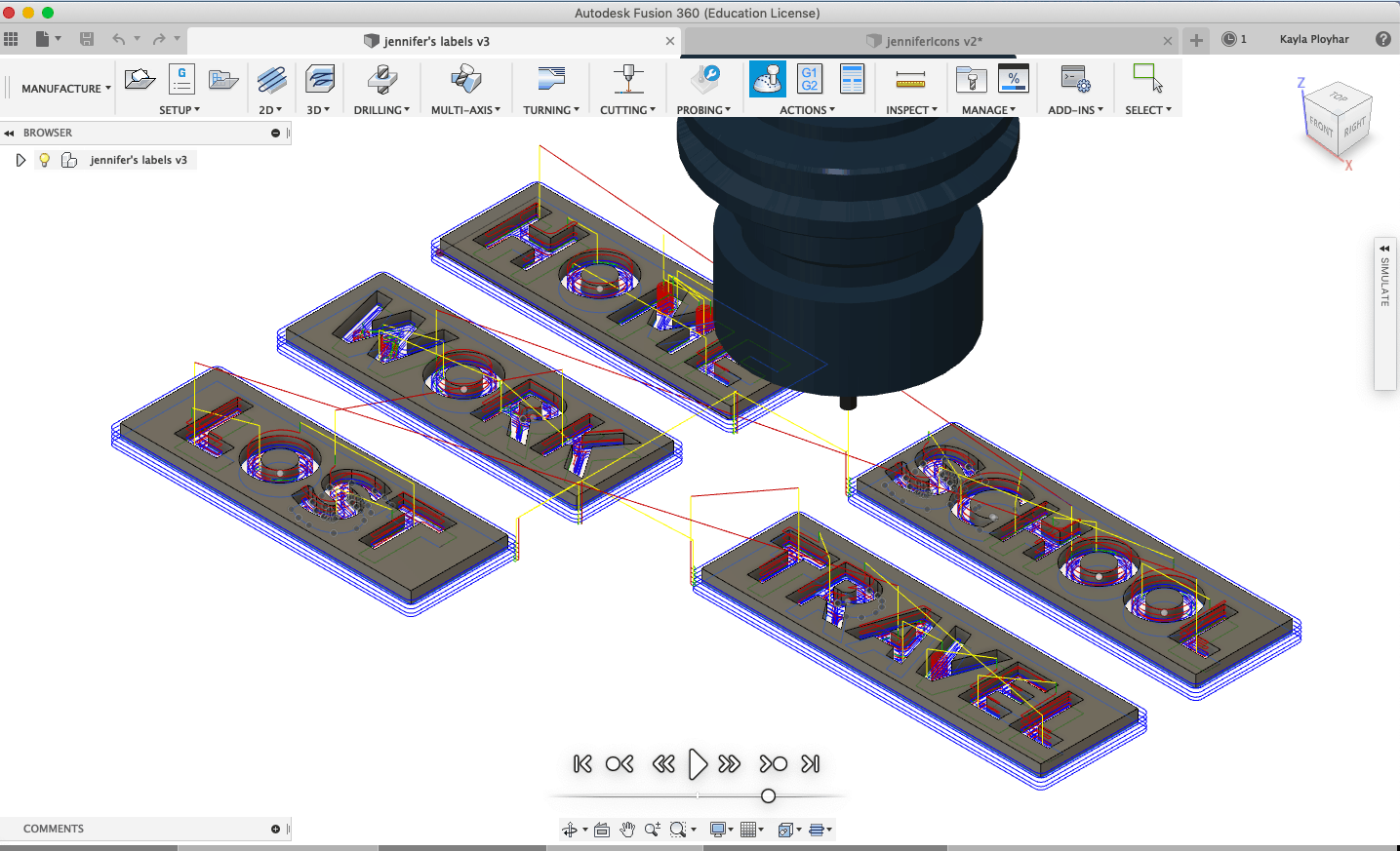
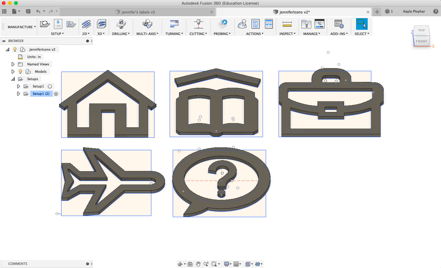
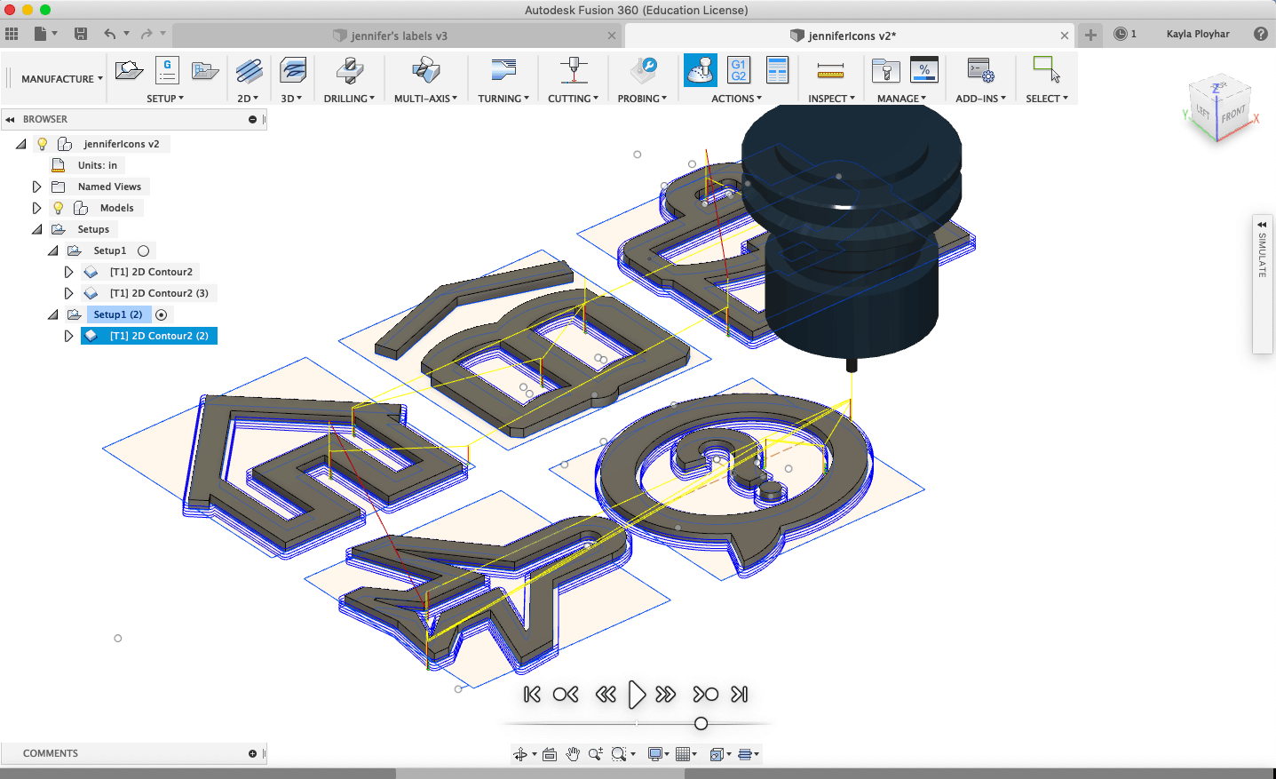
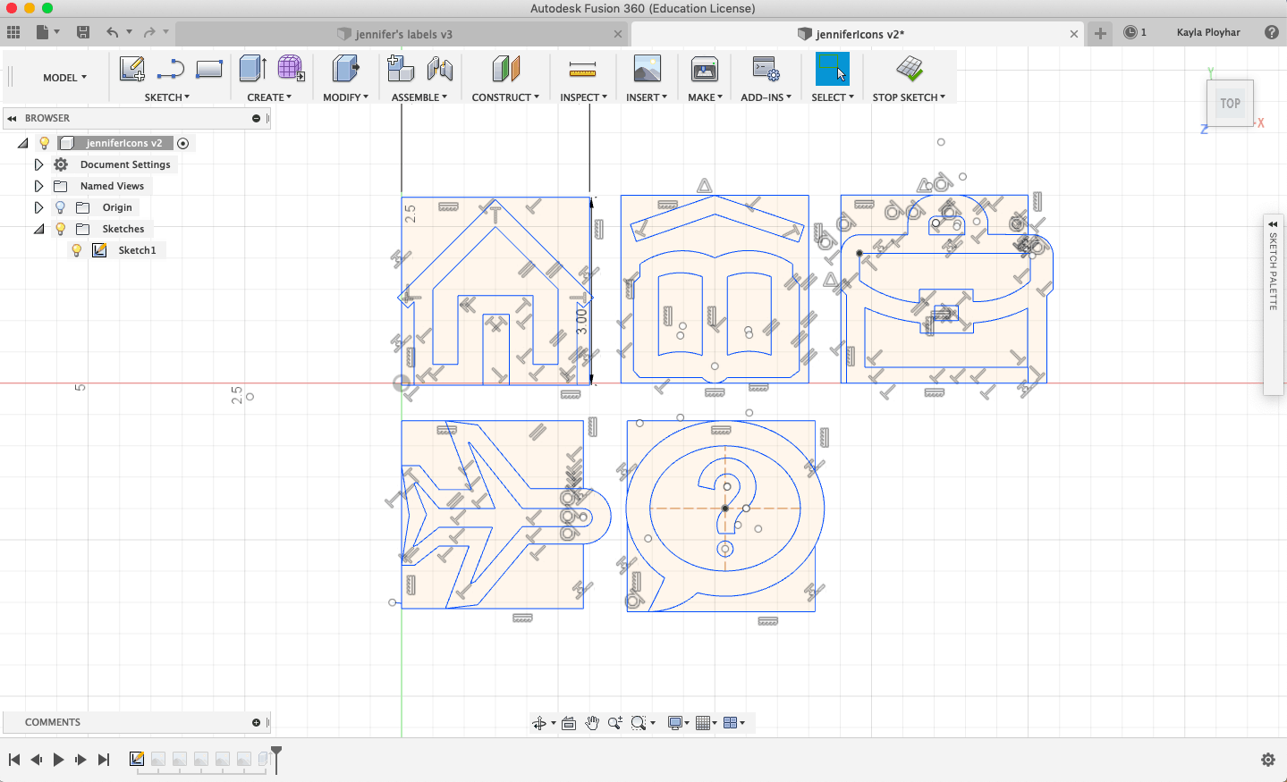
How it works: I used Autodesk’s Fusion 360, a cloud powered 3D CAD/CAM software, to design the location labels so that I could use the CNC to cut them out. CAD stands for Computer Aided Design and CAM stands for Computer Aided Manufacturing. The CNC I used was the Shapeoko CNC router, which is a hobby CNC router that uses a dremel as the machining head. The CAM software takes the design and converts it to G-code, which is what tells the CNC the exact x, y, and z coordinates of the parts that need to be cut out. Before cutting out any of the parts, I would mark a starting point for reference in case I ever needed to go back and restart, and I would home the machine by typing in “G10 L20 P1 X0 Y0 Z0” into the command module and then pressing “reset zero.” After cutting out my parts, I then spray painted the pieces and hot glued them to the backing. I also used the handsaw to cut out a small corner of the frame’s backing and then covered the rough edge with black electrical tape. This hole allows the wires from the LED strip to pass through and connect to the Particle, power source, and switch, which are all kept hidden behind the frame.
Since I initially planned on building my own frame, I had to learn how to use a handsaw to cut wood. This proved to be more time consuming and tedious than I initially thought, and the pieces I cut out were somewhat uneven and required a lot of effort to sand down. I eventually decided to purchase my own frame from Target to spare me the pain and time that came with building my own frame from scratch. I also encountered a few problems while designing my labels and while using the CNC, for instance, I had to manually adjust the widths of several of the letters because the letters were not wide enough for the tip of the drill. Additionally, we had to recut some of the icons because the machine cut the outline first before it cut out the inside cutouts, so when it got to cutting the inside part out, the icon went flying. We solved this problem by mapping out the path of the CNC first and getting the machine to cut the inside cutouts first before cutting the overall outline. However, as we tried to cut out the remaining icons the following day, the machine stopped working. The bit popped out of the dremel and we were unable to put the bit back in because the button to put the bit back in was broken. My remaining options were to either use the dremel to cut out the rest of the wooden icons or to simply make them out of paper, and I chose the latter to save time.
In the process of completing this milestone, I learned how saw using the handsaw and CAD using Autodesk Fusion 360.
In the future, I hope to add additional modifications, which is likely to be a couple OLED or LCD displays to display general information such as day of the week, date, time, and temperature.

SECOND MILESTONE
My second milestone for my main project was to set up the different recipes and location triggers on the IFTTT app and get the individual LEDs to change color based on the location of each member using the app.
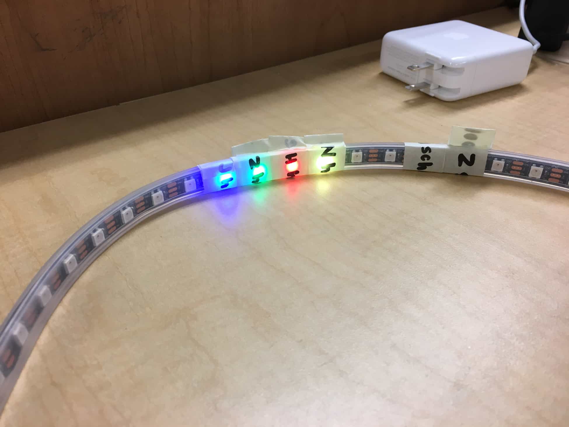
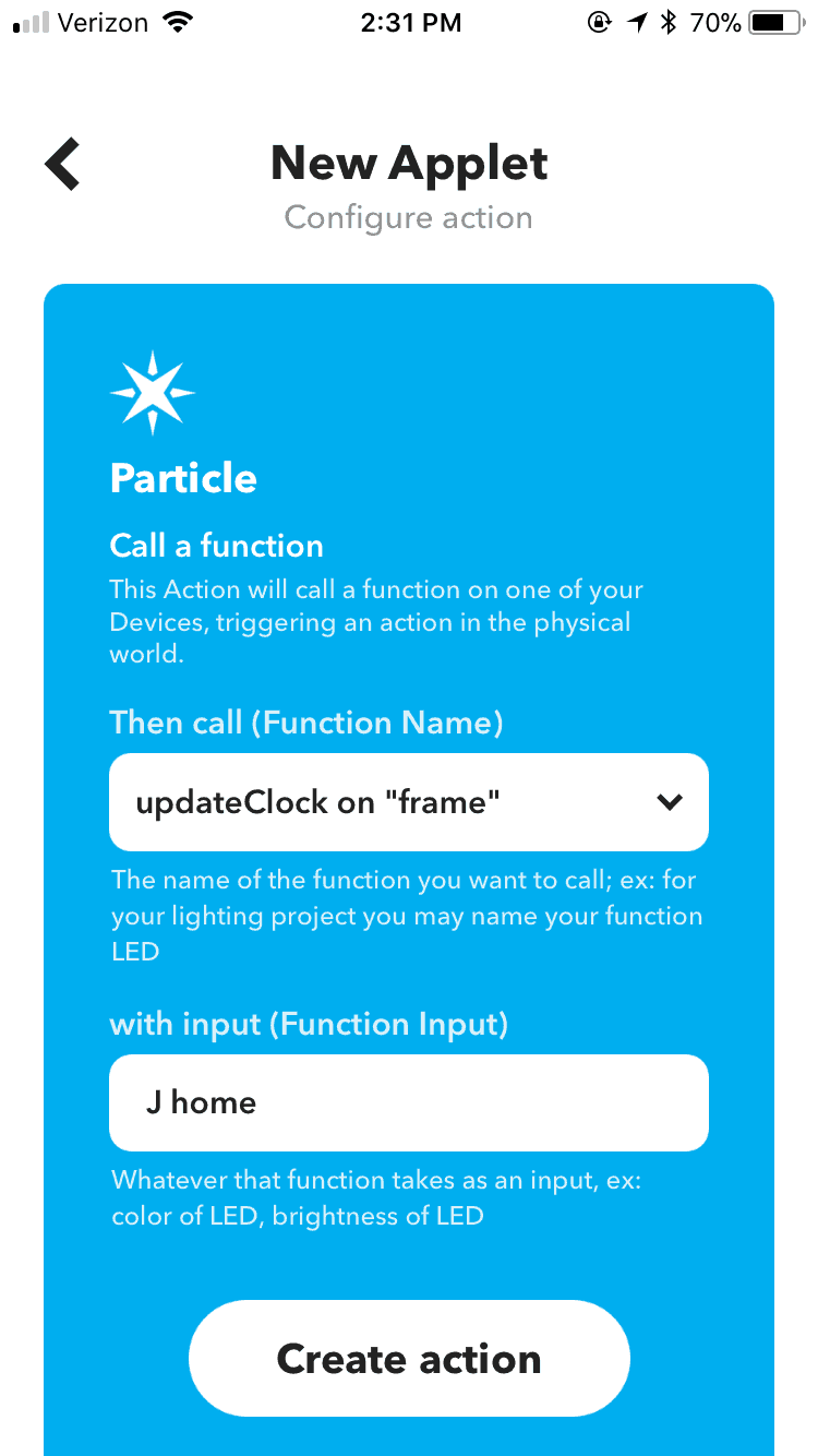
How it works: I downloaded an app on my phone called IFTTT, which stands for “if this, then that.” I created a few location triggers through this app that call a specific function on the Particle to update the lights on the LED strip. As long as the user allows it, the app continues to track his/her location and will update the Particle if there are any changes. I also downloaded this app on my parents’ phones and had to connect their IFTTT accounts to my Particle account before creating a few location triggers on their phones. To simulate what would happen if I were to change my location without leaving the campus, I set up a false trigger through the app. I set up an applet that I named “test button.” For the “this” condition, there is a trigger service called a button widget, which is simply a button that you can control from the app. For the “that” condition, I chose the function call from the Particle and set the input to the various locations and people I wanted to test. In order to access the button, I went to the applet and then to “Widget Settings,” and then pressed the button and watched a corresponding light light up in the LED strip based on the function input I set through the app. The Particle knows which lights to light up because of the code written in the Web IDE. I made a few modifications to the code I found online, for instance, I changed the number of family members from six to four, changed the names of the various locations, and I set the “default” position to home. I also included a switch to turn the Neopixels on and off by connecting one of the wires of the switch to a power source and the other to the light strip.
While this milestone was unexpectedly simple compared to my first milestone, I did encounter a couple minor struggles along the way. I had to figure out a different way to test the functionality of my project because I would not test the location sensing aspect without leaving the campus. As a result, I had to create numerous false triggers to test each Additionally, when I was testing my code in the beginning, I could not understand why specific lights were lighting up and why the color of the lights did not match what I had anticipated. This lack of understanding was partially due to the fact that I did not know how to code in C++, but also because I did not write the code myself, and had trouble following along with the original coder’s minimal comments.
Over time, by staring at my code and by running different tests, I was able to figure out the code and make the necessary modifications. I specifically learned that C++ has structs, which are useful for organizing data. I found several similarities between C++, which I had never learned, and Java, which I was already very familiar with. I also learned about soldering wires together and applying heat shrink in the process of integrating the on/off switch into my circuit.
My next milestone is to complete the rest of the project. This includes building the frame, which involves decorating and figuring out a way to keep the components secure, and adding potential modifications. For the modifications, I plan on adding an LCD display that can display general information that may be useful for whoever chooses to use the frame.
FIRST MILESTONE
The project I chose for my main project was the IoT Location Sensing Frame because it has both software and hardware components, and because I felt that it was more practical and could also be used outside of the program.
My first milestone was simply getting the Particle to control the LED strip, which I tested using code I found off the Core Electronics’ website.
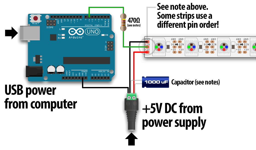
How it works: the Particle Photon is plugged into my laptop using a micro USB. This connection is used to power the Particle, but can also be useful in programming the Particle through the terminal on my Mac if the Particle is set to DFU mode. The Particle is connected to the breadboard to connect the various inputs from the LED strip to the pins on the Particle. I connected the DIN (data in) input from the LED strip to the D2 (digital 2) pin on the Particle and one of the GND (ground) inputs from the strip to one of the GND pads on the microcontroller board. I also attached a 1000 µF, 6.3 V electrolytic capacitor across the positive and negative terminals of the female jack power adapter to help reduce the ripple voltage. I attached the capacitor to the female power jack adapter by soldering each of the legs of the capacitor to male to male jumper wires. I then connected the power adapter to a 5V power source.
I encountered many struggles throughout the past few days in getting my project to function as I wanted it to, even having to redefine my milestones along the way. The first set of instructions I followed required me to use an MQTT broker and the OwnTracks app to keep track of each family member’s location. The original creator used an Intel Edison, which I had to replace with a Particle IoT Wifi Board because the production of the Edison is already discontinued. I copied the code from the Arduino files that came with the original instructions into the Particle IDE because they both use C++, and changed radius for region for each of the regions in the OwnTrack app for testing purposes. I also downloaded the app on another instructor’s phone to test if I could see her device under “Friends,” all before realizing that the problem was that neither device had successfully connected to the server to begin with. I went to the OwnTracks website to figure out how to set up my MQTT broker and looked at ratings and reviews for the OwnTrack app in the app store to find a potential solution to my connection problem. Both places suggested that I download Eclipse Mosquitto, an open source MQTT broker, and then either use Windows, Mac, Linux, a Raspberry Pi, or Ubuntu. I decided that this was not an optimal solution, and instead searched for other options I could use. After researching similar projects, I found that most projects that used a Particle Photon and location sensing used the IFTTT app to track location. I eventually found out what IFTTT was and realized that it was a much easier and developed option than the app and broker that I was initially using. I also struggled to connect the Particle to the wifi. The first time I connected my device, I had little trouble connecting it to an instructor’s hotspot. However, when I powered it on a couple days later, I could no longer connect it, and I kept getting an error message. Through many hours of troubleshooting, I was finally successful in connecting the Particle after disclaiming and reclaiming the device.
Throughout this project, I learned how to connect my Particle to the wifi using both the mobile app and the terminal on my Mac, and how to program the Neopixels using the Particle Web IDE.
My next milestone is setting up the IFTTT app and getting the individual LED’s to change color based on the location of each member using the app.
Attached is a schematic I found on the Adafruit Neopixels Guide. The only difference is that I used a Particle Photon instead of an Arduino.
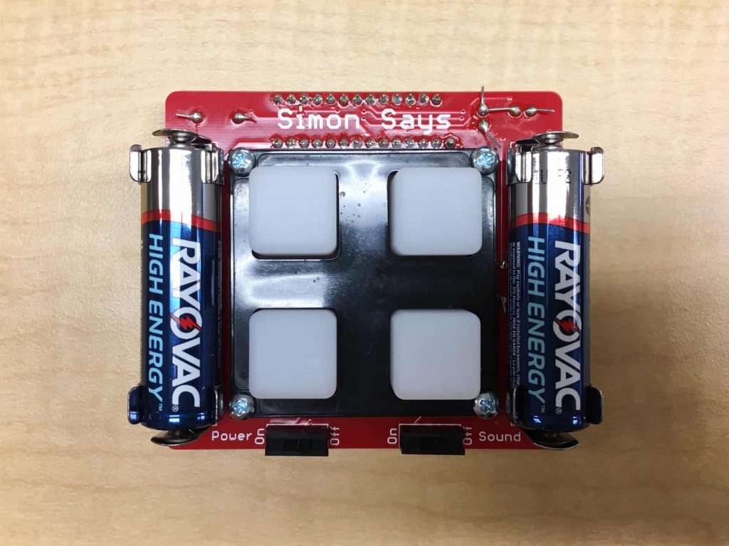
STARTER PROJECT: SIMON SAYS
I chose this game as my starter project because I thought it seemed like a fun game and that it would be fun to test. Additionally, it is a simple hardware build that allowed me to work on my soldering skills.
The game works as the name suggests. The board displays a sequence using the four different colored lights, and the user repeats the displayed sequence. The sequence continues to get increasingly complicated and lengthy as the game continues. If the user accidentally inputs an incorrect sequence, then the lights on the board start flashing and the user must press any one of the buttons to reset the game.
How it works: The board is a PCB board, which stands for a printed circuit board. There is a microcontroller that is programmed to light up the buttons and display the sequences, keep track of the user’s inputs, and know what to do when the user inputs an incorrect sequence. The 10 kΩ resistor controls the flow of current and the decoupling capacitors filter voltage spikes out of the voltage supply. Decoupling capacitors are also called bypass caps, and can act as a power source when there is a temporary drop in the power supply. The other parts, including the buzzer, battery clips, and switches, all work as suggested; the buzzer produces the sound, the battery clips hold the battery in place and are responsible for connecting the power source to the rest of the circuit, and the switches turn the game and the sound on and off. The LED lights, which stands for light emitting diode, are polarized because diodes only allow current to flow in one direction, are responsible for emitting the colored light for each of the buttons.
While working on this project, I learned how to solder and to be careful during soldering, avoiding accidentally burning nearby parts while trying to solder. The only struggle I encountered during assembly was early on in my soldering process when I accidentally pulled part of the covering off the PCB board, and had to start over.