Radio Controlled Hovercraft
| Engineer | School | Area of Interest | Grade |
|---|---|---|---|
|
Ethan F. |
Lynbrook High School |
Software and Electrical Engineer |
Rising Freshman |
FINAL MILESTONE
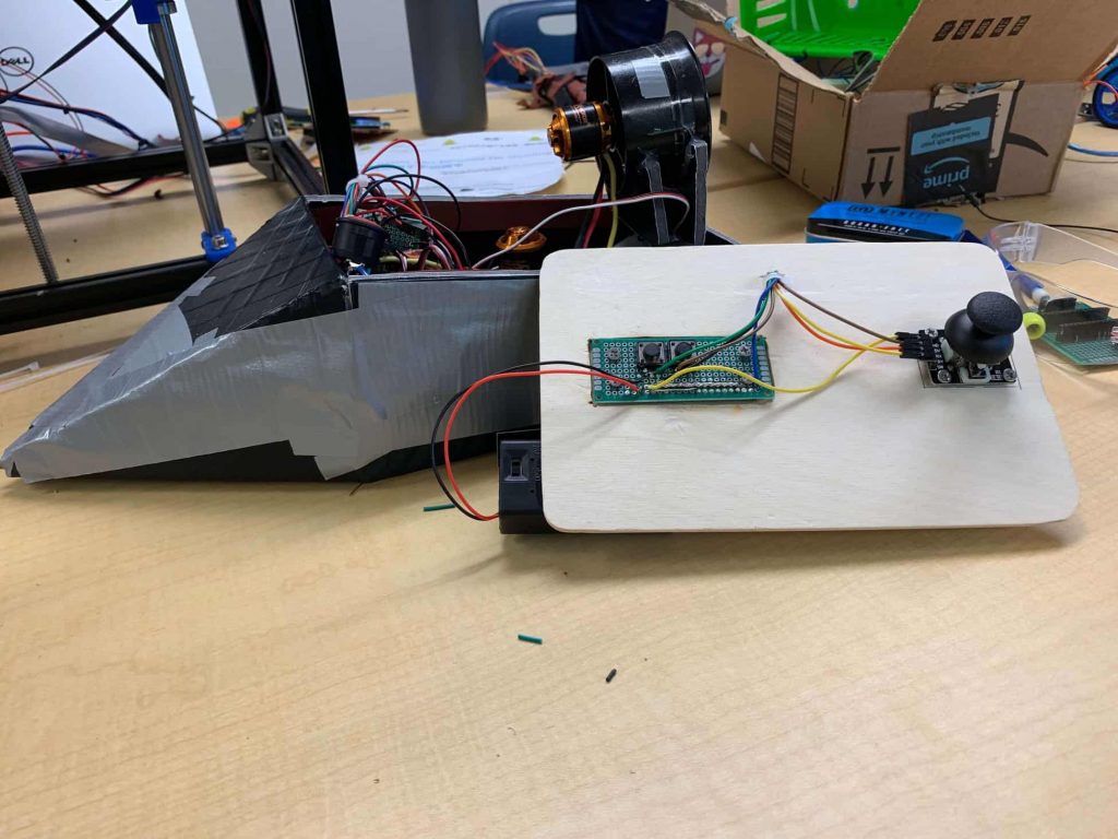
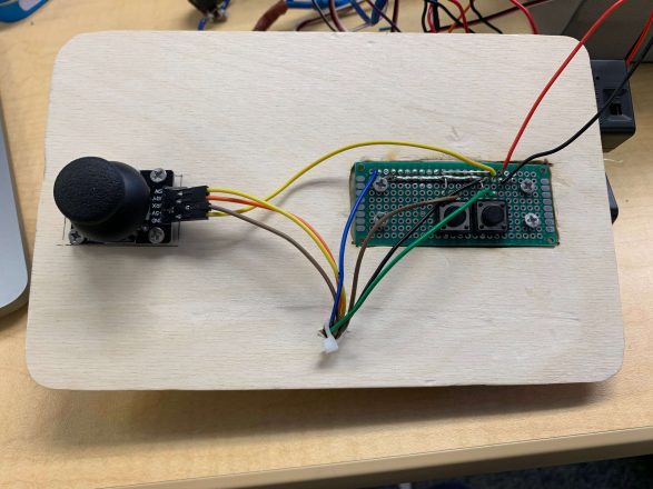
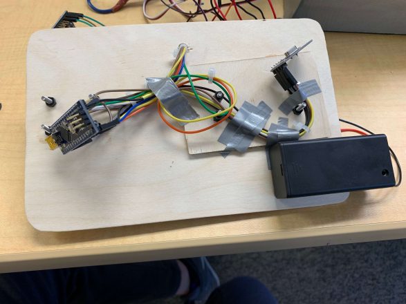
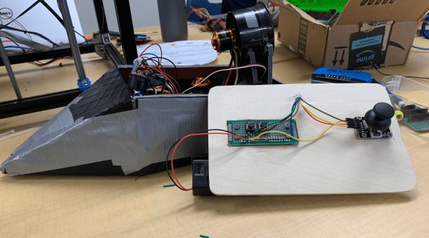
Friday June 12th, today I finished my final milestone, a.k.a my modification milestone. This time I took all my wireless connections and put it onto a piece of wood that acts as my controller. I also soldered all my wires onto a perf board to make the connections more stable and to prevent my wires from constantly detaching from their spots. On the receiving side of the NRF I have all my ground and power wires soldered to a perf board and had that connected to my ground and 5v pins on the nano respectively. Some of the problems I ran into while completing this milestone had to do with powering my arduino. Because I couldn’t keep my Nanos’ attached to my computer they needed an external power source. This power source was a 6v and 9v battery that I received. I took the two batteries and inserted them into my circuit to power the arduino. The greatest challenge that I faced had to do with trying to make rails on the perf boards. My controller had multiple components that needed to be connected to power and ground, because the nano did not have enough ground or power pins I had to connect the wires that needed to be grounded together on the perf board and then connect the ground wire from the nano to all the wires that needed to be grounded using solder (I had to do the same thing with the 5v power). My first thought was to make a solder bridge and have the wires that needed to be grounded/ powered to the soldered bridge. However after trying that with the first set of ground wires I found it very difficult, so with the other set of wires that needed to be connected I just used soldered them to small wires and attached the small wires together to make a rail, and then I attached the rail to my ground or 5v pin on my Nano. In the future I am hoping that I can attach a video camera to the front of the hovercraft and have that transmit a constant video feed to a console on the controller so that I can extend the range in which I can control the hovercraft.
Overall my experience at Bluestamp was awesome, there was a lot of learning that happened for me over the course of the camp. Also, the deviation from the traditional classroom learning style really allowed me to go at my own pace, and I felt this way it was much more relaxing and comfortable even though we did a lot of work each day.
THIRD MILESTONE
Monday, July 8th I finished my third milestone. This time I was able to wirelessly control my hovercraft with a joystick and two push buttons. The joystick controls the back motor and servo, so speed and direction. The push buttons just control how the hovercraft will hover, one push button for increasing motor rotation speed one for decreasing. I also used two NRF24L01, one as a wireless transmitter one as a receiver, because it can act as both. Then I connected these wireless modules to my Arduino Nanos, one for each. And the arduino Nano that was connected to the receiving NRF was then wired to the two ESC and a servo. Some challenges that I faced during my progression to my third milestone was dealing with the NRF24L01. Originally I had base modules on the NRFs which would regulate the voltage within it and provide for longer transmitting range, conveniently the base models labeled what each pin did. However, after a day of tinkering around with the NRFs I found that they just didn’t work, so I took them off. But, wiring directly to the NRFs proved much harder, as they had no labeling for the pins and my wires would constantly fall out resulting in me having to constantly rewire and check the connections between the NRFs and the Nanos. The push buttons I had also had some problems. The way in which the buttons were manufactured, caused it to be unable to touch the wiring beneath the bread board. I only figured this out after a day of testing the buttons, the problem was solved by slightly bending the metal ends of the push buttons to fit into the bread board. A few things I learned included the map(), constrain(), and PULL_UP function arduino has. Map will take two ranges and make the first range proportional to the second range. This function was really useful in my case, because my joystick had a range of 0 – 1023, but the servo motor that was on the back of my hovercraft had a range of 0º – 180º, because it was an 180º servo. The constrain function works in sync with the map function. In the case that there is a reading error and the map function accidentally maps the value outside the set of possible ranges, the constrain function will be there to literally constrain the specified value to be in between the possible range of numbers. For example it is not possible for the servo motor to turn to 270º, so if the map function outputs this value the constrain the function will lower it until its a degree that is possible for the servo motor to turn to. PULL_UP just activates the built-in resistor arduino has in all of its digital and analog pins. PULL_UP allowed me to get rid of a resistor as a voltage divider. The wiring on my controller at this point looked like a jungle so getting rid of two power wires helped a bit with the amount of wires that would be constantly falling out. My next steps would probably be tidying up the wiring and making an actual controller in which the two push buttons and joystick would be situated on; as well as converting all the wiring onto a pref board and soldering them in.

SECOND MILESTONE
Friday, June 28th I have finished my second milestone and my project. I have a hovercraft that can hover and turn following the commands of my controller. The hovercraft body is consisted of rectangular and triangular shapes made of plastic depron. On the right is a 2d view of my hovercraft. Some of the challenges I had when making the body is cutting the exact shape in order for the pieces of the body to fit together. For most of the pieces it took me two or more attempts in order to get the right shape. And then I used hot glue to hold the pieces together. After finishing the body, I taped and glued the motors into their respective positions (represented in the diagram in red). The blue part of the diagram is the servo that the rear motor is mounted on to control steering. The orange part of the diagram is an elevated platform in which the motor that controls the hovering is mounted on so that it does not protrude into the skirt that exists on the bottom of the hovercraft. I made the skirt on the bottom of the hovercraft with tent fabric. It was made by cutting a rough outline of the base of the hovercraft and then cutting slits in the corners, so that the skirt would fit nicely onto the base of the hovercraft. After that I used duct tape to secure the skirt onto the hovercraft. My first attempt on making the skirt didn’t go so well, because the skirt was too loose, so on my second attempt I made sure to have the skirt hug tightly against the hovercraft. And after that I used a soldering iron to poke holes in the skirt to direct air flow for the hovercraft to hover.

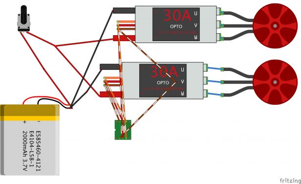
FIRST MILESTONE
Thursday, June 20th, today I have finished my first milestone. I have accomplished spinning the brushless dc motors with the radio controller. The schematic I made on fritzing is not exact, some of the parts are not correctly labeled, i.e I have a 40A brushless ESC motor not a 30A, but the basic circuit design is there. The circuit includes a power switch for safety reasons, 2.4GHz receiver, a 20c lipo battery, two 40A ESC, and 2 brushless dc motors. There is also a lot of soldered wires in the actual design used to extend the range in which the motors could be placed from the battery. Here is my understanding on how the whole design functions. First the two brushless ESC motors are able to control the speed in which the motor turns at by using a MOSFET and diode. The MOSFET acts as an on and off switch, and when it turns on the current rises as the magnetic fields in the windings of the motor increases. When the MOSFET turns off the magnetic energy in the windings in the of the motor are slowly absorbed by the ESC, and by cabling a diode across the motor which will return the energy of the magnetic field back into a current which slowly declines as the magnetic field weakens. The MOSFET will turn on and off roughly 2000 times second, which makes the DC current look similar to an AC current. The combination of diode and MOSFET actually provides the brushless DC motor with an AC current. The brushless dc motors are able to spin because of the octagonal wiring inside. The wiring will run different currents through the wire which will attract the magnets that are attached to the piece of metal which turns the fans on the motor. Because there is no actual contact between the motor and the part that spins the motor, the motor is categorized as brushless.
MOTION ALARM
My starter project is the motion alarm. What it does is pretty simple. The ultrasonic sensor will sense if there is an object in front of it; and based on that it would notify the Arduino Uno board. The Arduino Uno board would then tell the RGB LED light to change color, the piezo buzzer to make a sound, and the servo motor to turn a certain number of degrees.
-
THE RGB LED LIGHT
The colors in a LED light are controlled based on PWM (Pulse Width Modulation). Typically a PWM value of 0.0 would turn the specific color light in the LED off, there are three different RGB lights, and three different PWM values. 1.0 would turn the LED on to full power. In order to change the intensity of the LED you would for example pulse the PWM signal at full power 30% of the time, because the light is blinking so fast you would perceive it as the light being dim at 30%. Same for 70% brightness, you would pulse the PWM at full power 70% of the time.
-
SERVO MOTOR V.S REG. MOTOR
Servo motors can tell the position in which they are at. While regular motors are based off of the speed and velocity in which the motors is spinning, servo motors are all about the position in which the motor is at.
-
¿PIEZO BUZZER?
A piezo buzzer functions by sending an electric current through a special element that it houses. The material will deform and form back at the same speed as the voltage of the AC signal, which would produce an audible sound.
-
F(X) = ULTRASONIC SENSOR
The sensor sends out a sound wave and calculates the distance in which the object is sensed by multiplying the time it takes for the wave to come back to the speed of the wave divided by two to get the distance.