Clarissa L. | BlueStamp Engineering

Clarissa L.

Solar Powered Raspberry Pi Camera

My main project is a solar-powered Raspberry Pi camera. This camera is able to take a timelapse and it does not require to be plugged into any wall power connectors as it is solar powered.
Engineer School Area of Interest Grade
Clarissa L.
The Spence School
Engineering
Incoming Freshman

Reflection

I really enjoyed the time I spent at BlueStamp and it was a great introduction into engineering. I learned a lot working on this project and I’m glad I joined this program. Through this program I gained more confidence regarding engineering and I had a lot of fun!

FINAL MILESTONE

For the third milestone I attached the solar pi platter, solar panel and the battery that would be charged by the solar panel to the rest of my project. The raspberry pi zero attaches on top of the pi platter and connects though 4 metal spring pins as seen in figure 2. The solar panel is attached to the pi platter as well as the battery it charges which then powers the raspberry pi that is attached as seen in figure 1. I then uploaded the code for the time-lapse to the raspberry pi. In order to take a timelapse I had to use a feature on the pi platter called Real Time Clock (RTC) which could track the current time and date. This feature was crucial to coding a time-lapse because it allowed the raspberry pi to schedule when to take the next picture for the timelapse. 

To start a timelapse you would turn the switch off (notice in figure 1) which tells the pi to start the code that is already uploaded onto it. The code basically tells the camera to turn on take a photo then turn off in one minute intervals. These pictures will then show up in a folder on the pi which can later be combined to create a timelapse. If you turn this switch on it will run the pi as a normal raspberry pi.

One issue I had was that I had trouble connecting the pi platter and raspberry pi, notice this connection in figure 2. I tried many different processes such as attaching the ground, 3.3 volt and 5 volt pins together with wires in the corresponding pins on the raspberry pi 3 and the pi platter. This created a line of power that flowed from the raspberry pi to the pi platter where I was trying to get the pi platter to charge the raspberry pi. I also tried finding specific wires that would attach from the pi platter to the rpi but, in the end when I tried to program on the rpi it said that the pi platter, “could not be found.” After visiting many sites about the solar pi platter and the connections between it and rpi I could only find information regarding the rpi zero edition. This led me to resulting in switching from the rpi 3, which was not connecting, and to the rpi zero. 

From this milestone I learned more about the solar pi platter and solar panels. I learned how solar panels work to create energy to then be stored in a battery that powers the rest. I learned that something like a pi platter is needed to also transport and store the energy from one place to another. I also learned a little about python, how to schedule when to take a picture using the RTC from the pi platter and how to preview the images from the camera onto a monitor screen. 

Overall this project was really fun and rewarding in the end although it was challenging at some times. 

The second milestone of my main project was to get the camera to stream. I attached a camera module to the raspberry pi which captures whatever it sees and sends it to the raspberry pi which then streams the display on the screen (shown in figure 1.)

The code I used to get the camera to stream is found in figure 2. I used this website (link here: https://picamera.readthedocs.io/en/release-1.13/recipes1.html) to help me code the camera. In lines 1 and 2 the language “from… import” is used. This language tells us to measure sleep in time and to use picamera, the raspberry pi program for connecting a camera. It then names the PiCamera as just camera. In line 5 the code resizes the size of whatever you would be recording. In line 6 the language “start_preview” starts the streaming of the camera onto the screen without recording anything. In line 8 it says “sleep(2)” which causes the camera to “sleep” or wait for 2 seconds before starting up.


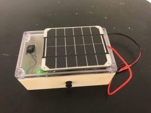
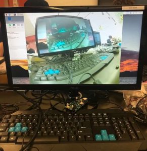
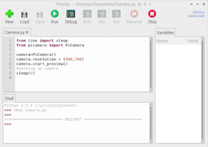
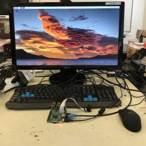
          From this milestone I learned a little about how to control the camera with python. One issue I had was that when I first started streaming the camera, everything was very blurry. I twisted the focus on the camera module and it gradually became more and more into focus, in figure 1 you can see what it looks like after it was in focus.

SECOND MILESTONE

FIRST MILESTONE

 The first milestone of my main project, a solar-powered raspberry pi camera, was just setting up the raspberry pi and getting it to work. A raspberry pi is a type of computer, that I am using for this project.To get this raspberry pi to work I had to download a software called NOOBS (New Out Of Box Software: https://www.raspberrypi.org/downloads/noobs/) and transfer it from the computer onto the microSD card that would be inserted into my raspberry pi (notice in the top of figure 2). The NOOBS software contains the operating system, raspbian, needed to run the computer. I then inserted the microSD card into my raspberry pi and plugged in the mouse, keyboard and HDMI cable into the corresponding slots on the raspberry pi (notice in figure 1). Lastly I plugged in the power and a red light and a blinking green one came on signaling the working program. 

The raspberry pi then booted on the monitor and it was set up (seen in figure 3). From this first milestone I learned what raspberry pi is and how it works. One trouble I had with this milestone is that for a long time the raspberry pi program was not booting. I tried many different ways to solve this issue such as wiping my SD card, playing around with the cords and even putting different files onto my microSD card. Finally I tried inserting someone else’s microSD card in and the raspberry pi booted successfully resulting in my realization that my SD card was the issue. I solved this by obtaining a fresh card and it worked! Another minor issue is that I transferred the NOOBS software to the card as one folder instead of transferring the contents of the folders, this was easily solved. Although this milestone was very frustrating when the raspberry pi would not boot, this step was vital to my project as a whole and I’m excited to continue!

STARTER PROJECT

    My starter project is Simon Says (https://www.sparkfun.com/products/10547). Notice in Figure 1 the four LEDs (light emitting diode: one-way light emitters) hidden behind four buttons that light up accordingly with different colors. The machine will display a random pattern that increases with one light each round. Each round, as the pattern increases, the player has to repeat the pattern by pressing the buttons in the correct order. When the player fails to repeat the pattern perfectly the buzzer will buzz and you lose the game. The game will then reset and the player can try again. Through this project I learned how to use polarized components, such as a LED and a battery, that have a positive and negative side and therefore a specific order that it has to be placed in. The project also has two on and off switches which control the flow of electricity through the two batteries along the side (these can be found at the bottom of Figure 1). One of the batteries controls the LEDs and the other controls the buzzer. In Figure 2, notice the microcontroller at the top which contains all the code needed to run the game. The microcontroller is what controls the entire game and without it nothing would run.

            Through this project, I learned how to solder and put together all the pieces to fit on the printable circuit board. One mistake I made is that sometimes I forgot to touch the soldering iron to both the hole on the board and the wire so the solder tended to avoid the hole and climb up the wire instead. This issue could easily be solved if I just heated the solder up again and brought it down to the hole. Overall this project was really fun and helped me learn the basics to continue on into my main project.

Stay Connected to BlueStamp