The Laser Harp
My intensive project is a laser harp. The harp consists of six laser modules and six photodiodes that are pointed towards each other. Once a laser beam is broken, a specific note plays via an Arduino. The harp plays six different notes at various pitches and sounds. Modifications to the project include adding a wave shield and speaker to the Arduino and making a PVC pipe frame for the harp.
| Engineer | School | Area of Interest | Grade |
|---|---|---|---|
|
Alex U. |
The Urban School of San Francisco |
Mechanical Engineering, Genetic Engineering, Biology |
Incoming Senior |
REFLECTION
Over the course of making the laser harp, I worked with Arduino, electrical wiring, mechanical construction, and wave shield. Before starting Bluestamp, I had the goals of gaining a better understanding of coding and to get more experience with building things. Not only did I confidently reach these goals, but I gained an arsenal of life skills as well. Building the laser harp fulfilled my desire to combine music and engineering/electronics to make a completely electric instrument. Building the harp has solidified the conception that being passionate about what one is doing makes the experience exponentially more fun. I have learned how to be an expert troubleshooter and how to interact with my peers and instructors in order to achieve a goal. I am very grateful to have had the chance to attend Bluestamp, as it has helped me make up my mind about the path that I want to lead going forward.
FINAL MILESTONE
HOW IT WORKS
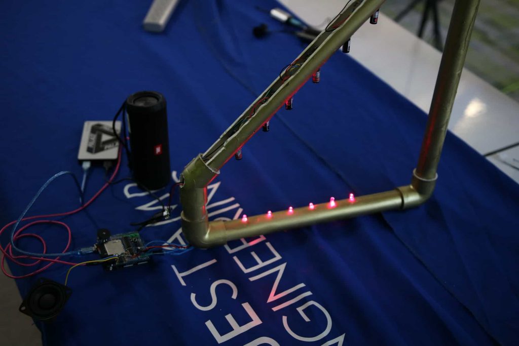
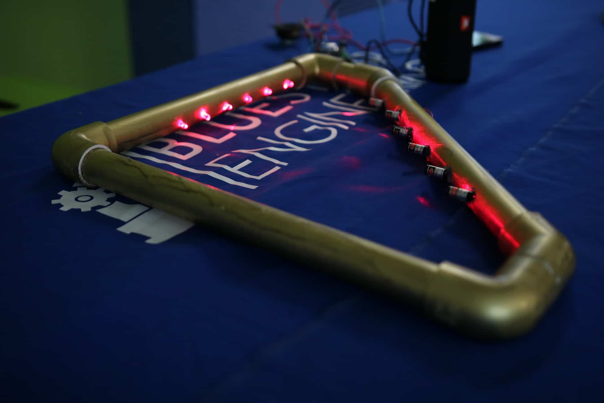
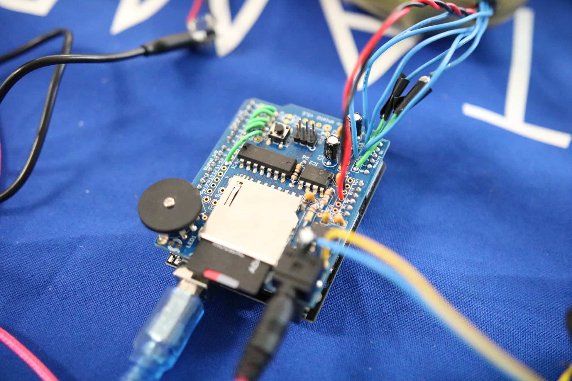
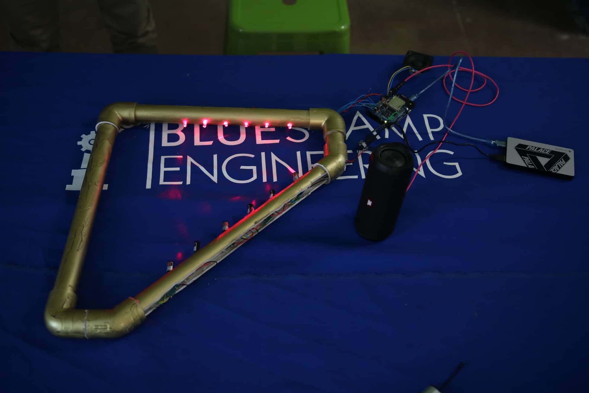
For my third and final milestone, I inserted the wiring from my second milestone into a harp that I constructed with PVC pipes. I had two modifications in this milestone: the PVC pipe frame and the wave shield. I constructed the frame with four pieces of PVC and 5 PVC pipe fittings. I used two 90° fittings at the base, one 135° on the short leg, and one 135° + one 90° fitting connecting the long leg and the “hypotenuse” of the frame. My intention with this frame was to have the alignment of lasers and photodiodes be as precise and permanent as possible. I did this by drilling holes on the same line on the base of the frame and the “hypotenuse”. The photodiodes are spaced 1.5” from each other on the base, and the lasers are also spaced 1.5” from each other on the opposing pipe. After drilling holes, I cut ~1 inch of the pipes’ diameter off so that there would be an opening in the pipe on the other side of the holes. I inserted my wiring into the pipes that I had drilled holes into. Once they were lined up directly, I hot glued both electrical components into their given positions to ensure a constant amount of light being detected by the photodiodes. I also completed a wave shield by soldering all of its electrical components onto its circuit board. The wave shield snaps onto the Arduino via extended pins and allows the Arduino to play noises that it cannot play on its own. I did this by converting 6 wave files from an archived wave file website into my iTunes account. This enabled me to upload the files onto an SD which I then inserted back into the wave shield. Since I have 6 notes on my harp, the wave files were 6 different notes, all in harp noise. Both the lasers and the Arduino/wave shield are powered by the USB ports on a 5V portable charger. I also connected the wave shield to a larger speaker via an auxiliary cord so that I could amplify the noise being produced by the harp. Overall, making this harp was super fun and it has made me want to continue to build in the future.
#include “WaveUtil.h”
#include “WaveHC.h”
SdReader card; // This object holds the information for the card
FatVolume vol; // This holds the information for the partition on the card
FatReader root; // This holds the information for the filesystem on the card
FatReader f;
uint8_t dirLevel; // indent level for file/dir names (for prettyprinting)
dir_t dirBuf; // buffer for directory reads
WaveHC wave; // This is the only wave (audio) object, since we will only play one at a time
const int notes = 6; // there are 6 notes in total
int scale[notes] = {0,2,4,5,7,9}; // these are the 6 notes
int threshold = 10; // the value that a laser needs to be expressing in order to play a note msut be below 35
bool debugMode = false; // debugMode is either true or false
int notePlaying = 10;
#define C 3830 // 261 Hz
#define D 3400 // 294 Hz
#define E 3038 // 329 Hz
#define F 2864 // 349 Hz
#define G 2550 // 392 Hz
#define A 2272 // 440 Hz
void setup() {
Serial.begin(9600); // the BAUD rate in which data is being refreshed and uploaded is 9600
putstring_nl(“nWave test!”); // say we woke up!
//putstring(“Free RAM: “); // This can help with debugging, running out of RAM is bad
//Serial.println(freeRam());
// Set the output pins for the DAC control. This pins are defined in the library
pinMode(2, OUTPUT);
pinMode(3, OUTPUT);
pinMode(4, OUTPUT);
pinMode(5, OUTPUT);
// if (!card.init(true)) { //play with 4 MHz spi if 8MHz isn’t working for you
if (!card.init()) { //play with 8 MHz spi (default faster!)
putstring_nl(“Card init. failed!”); // Something went wrong, lets print out why
//sdErrorCheck();
while(1); // then ‘halt’ – do nothing!
}
// enable optimize read – some cards may timeout. Disable if you’re having problems
card.partialBlockRead(true);
// Now we will look for a FAT partition!
uint8_t part;
for (part = 0; part < 5; part++) { // we have up to 5 slots to look in
if (vol.init(card, part))
break; // we found one, lets bail
}
if (part == 5) { // if we ended up not finding one 🙁
putstring_nl(“No valid FAT partition!”);
//sdErrorCheck(); // Something went wrong, lets print out why
while(1); // then ‘halt’ – do nothing!
}
// Lets tell the user about what we found
putstring(“Using partition “);
Serial.print(part, DEC);
putstring(“, type is FAT”);
Serial.println(vol.fatType(),DEC); // FAT16 or FAT32?
// Try to open the root directory
if (!root.openRoot(vol)) {
putstring_nl(“Can’t open root dir!”); // Something went wrong,
while(1); // then ‘halt’ – do nothing!
}
// Whew! We got past the tough parts.
putstring_nl(“Files found:”);
dirLevel = 0;
// Print out all of the files in all the directories.
//lsR(root);
}
void loop() { // put your main code here, to run repeatedly:
for(int i = 0;i < 6;i++){ // Says that i’s initial value is 0; i is always less than 6 (0-5);for each loop, 1 is added to i . if(debugMode) // if debugMode is true…
{
Serial.print(“A”); // A is printed at start of serial monitor
Serial.print(i); // Whatever i is is printed right after A
Serial.print(“: “); // Colon is printed after “Ai”
Serial.print(analogRead(i)); // The anbalog value of i is read and printed on serial monitor after “Ai:”
if(i==5) // conditional statement: if i == 5…
{
Serial.println(); // once i = 5, a new line is printed with the next values of A0-A5
}
else // if i != 5 (is not equal to 5)…
{
Serial.print(” “); // more space is printed to the right of the “Ai:analogRead(i)” value so that the next “Ai” value can be printed, until A5 is reached
}
}
if(analogRead(i)< threshold) // conditional statement: if the analogRead value of i is less than the threshold… { Serial.print(“Laser A”); // the serial monitor prints “Laser A” Serial.print(i); // then it prints whichever i is Serial.println(” plays note “); // “plays note” is printed after the given value of Ai, and then a new line is printed to signify the length at which a note is being played for if (notePlaying != i) { notePlaying = i; switch (i) { case 0: playfile(“pianoA.wav”); //tone(speakerOut, C, 10); break; case 1: playfile(“pianoB.wav”); //tone(speakerOut, D, 10); break; case 2: playfile(“pianoC.wav”); //tone(speakerOut, E, 10); break; case 3: playfile(“pianoD.wav”); //tone(speakerOut, F, 10); break; case 4: playfile(“pianoE.wav”); //tone(speakerOut, G, 10); break; case 5: playfile(“pianoF.wav”); //tone(speakerOut, A, 10); break; } } } } if (analogRead(notePlaying) > threshold) {
notePlaying = 10;
}
delay(5); // a delay of 5 hundreths of a second occurs between each loop of the void
}
// Plays a full file from beginning to end with no pause.
void playcomplete(char *name) {
// call our helper to find and play this name
playfile(name);
while (wave.isplaying) {
// do nothing while its playing
}
// now its done playing
}
void playfile(char *name) {
// see if the wave object is currently doing something
if (wave.isplaying) {// already playing something, so stop it!
wave.stop(); // stop it
}
// look in the root directory and open the file
if (!f.open(root, name)) {
putstring(“Couldn’t open file “); Serial.print(name); return;
}
// OK read the file and turn it into a wave object
if (!wave.create(f)) {
putstring_nl(“Not a valid WAV”); return;
}
// ok time to play! start playback
wave.play();
}
SECOND MILESTONE
HOW IT WORKS
For my second milestone of the laser harp, I wired all of my electrical components and added a piezo buzzer to the end of the photodiodes. At first, I converted my singular breadboard from my first milestone into two breadboards; one for the lasers and one for the photodiodes. Then I realized that I cannot fit breadboards into the PVC pipe frame that I intend to make for my final milestone. In order to get rid of the breadboards, I started by cutting perf boards into 13 small 6 by 6 hole pieces (one for each laser and photodiode and one piezo buzzer). For my power source for the lasers, I found a 5V portable charger and soldered a micro USB→leads adapter to it so that I could insert those leads into the first perf board. Next, I soldered a 100 ohm resistor to the negative lead of one of my laser modules and soldered it into the same column as the “ground” lead. After soldering the positive lead of the laser module into the “power” lead column, I mimicked the positive and negative electrical connections that breadboards have by soldering a wire along the ground and power columns. I made sure to solder both wires so that they touched each electrical component in that column, carrying the electrical current forward. Finally, I soldered two more leads to the end of the perf board and soldered the ends of those leads to the opposing columns of the next perf board. I did this until all 6 lasers turned on when I connected them to the charger. The photodiodes are wired in the same manner, except a long wire was needed to run from each individual perf board to the analog pins on the Arduino. I soldered this wire in series with the 100 ohm resistor and the short lead of the photodiode. Finally, the piezo buzzer resides on the last perf board on the string of photodiodes. I added an output to my previous code on digital pin 9, which is where the piezo buzzer goes to. The piezo buzzer is pertinent to this milestone, as it allows the harp to actually play and not just detect which note is being played on the serial monitor. Going forward, I am excited to insert all of my complex wiring into the PVC pipe frame that I am going to build.
CLOSE UP
FIRST MILESTONE
HOW IT WORKS
For my intensive project, I am making a laser harp. The basic function of the project is to play a note when a laser beam is broken. For my first milestone, the harp is made up of 6 lasers and 6 light sensing photodiodes. Each laser is pointed directly at the center of each tip of their corresponding photodiode. Positioned on the same breadboard, both photodiodes and laser modules are in series with 100Ω resistors. Since photodiodes more effectively convert light energy into current when they are in a reverse biased orientation, I made sure to put the longer lead (usually the positive lead) into the ground power supply and the shorter lead into the positive 5V position. I would like to scale the project up by moving the lasers to a separate breadboard that is parallel to the breadboard with photodiodes and the Arduino. I connected each photodiode to the 6 analog pins on the Arduino (A0-A5). This allowed me to retrieve serial monitor readings from each photodiode. Since photodiodes sense light, the serial monitor readings were an expression of how much light each photodiode is picking up from the lasers. These readings were represented in values from 0 to 1024. In order to get the serial monitor to show when a note is being played, I made a threshold value in my code of 35. When the lasers were on target with the sensor inside of the photodiodes, the serial monitor value for each laser-photodiode pair was ~300. If the serial monitor value dropped below the threshold then the laser beam was broken/blocked. If the laser is broken/blocked, then a laser has been “strummed” and a note will play. The hardest part about achieving this first milestone was keeping the lasers pointed consistently and perfectly at the tip of the photodiodes. If the laser module was touched or moved, even by a millimeter, the beam could skew away from the photodiode sensor. The serial monitor value could accidentally drop below the threshold value, falsely playing a note at the wrong time. Going forward, I would like to add a speaker and eventually build a frame for the electrical components so that my project can take the shape of an actual harp.
STARTER PROJECT: THE USELESS MACHINE
HOW IT WORKS
The batteries power a mechanical arm that flips the protruding switch back to its original position. Once the switch is flipped by the user the circuit becomes closed, inducing a current that flows in the direction from the battery pack to the PCB. Once the current hits the PCB, it goes across the bicolor LED in one direction, making the LED green (one of its two colors). Subsequently, the current flows into the motor, which is attached to the mechanical arm, pushing the arm out of the box and in the direction of the protruding switch to flip it back. When the arm begins to move up, the snap switch is released, signifying that the arm is out of its original position. Once the arm has flipped the switch, the current has reached the end of the circuit and begins to flow back towards the battery pack. As the current passes back through the circuit, the motor turns in the opposite direction, bringing the arm back down, and the bicolor LED turns from green to red. While the arm is coming back down, the snap switch slowly becomes closed, communicating to the motor that it must stop in order to return the arm to its original position. This opens the circuit once again, awaiting to be uselessly flipped until the end of time.
SCHEMATIC DESIGN
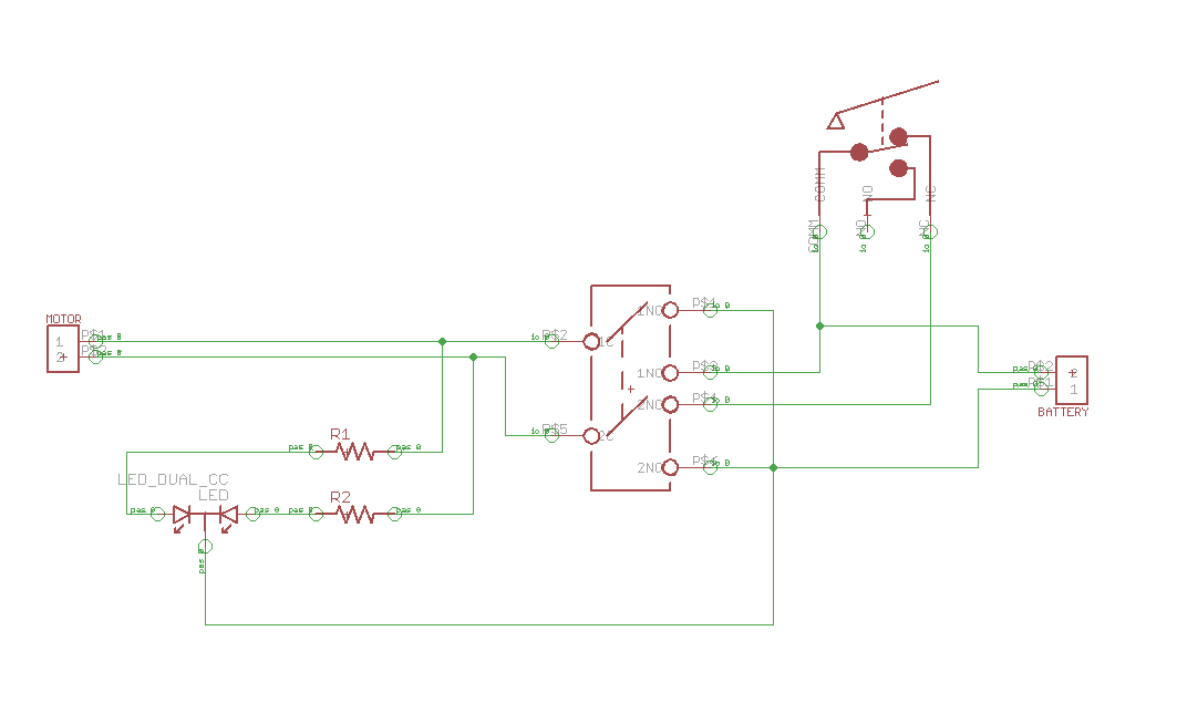
The Useless Machine is indeed very useless, as its only function is to flip a switch to its original position after the user has primarily flipped it. Besides from the plastic casing and corner posts, the machine is made up of a motor, a switch, an acrylic arm, a printed circuit board (PCB), a bicolor LED, a 100Ω resistor, a 220Ω resistor, and a snap switch. It is powered by a battery pack with three AA batteries, giving the machine the power of 4.5 volts. The purpose of this machine is useless, yet the concept of making something so simple through an intriguing and complex process gives it more meaning than may be perceivable.