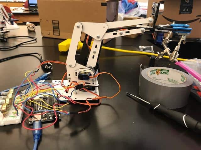
Robotic Arm with a Claw
There are 3 components to the Magic Mirror: The mirror, the monitor, and the frame. The monitor is powered by a Raspberry Pi 3 that displays the Magic Mirror interface. The frame encases both the mirror and monitor to create the Magic Mirror illusion.
| Engineer | School | Area of Interest | Grade |
|---|---|---|---|
|
Alex C. |
Regis High School |
Engineering |
Rising sophomore |
SECOND MILESTONE
For my second milestone, I modified with an ultrasonic sensor. Ultrasonic sensors sense the distance to another object. They send out sound waves that humans can’t hear, and the sound waves bounce off of objects and are received by the ultrasonic sensor. Based on the time it takes to receive the signal after sending it out, the sensor can calculate distance.
Using the ultrasonic sensor, I modified my code to make it fully autonomous. The base sweeps around to search for objects, and if there is an object within 15 cm, it stops and extends the arm until the object is within 5 cm. Then, it grabs the object, and when it is closer than 3 cm, the arm retracts, bringing the object back.
Writing the code for this project was very challenging. I learned a lot about coding for ultrasonic sensors.
FIRST MILESTONE
My first milestone was to program and assemble the arm so that 4 servo motors could move it’s 4 joints. They each turn 180 degrees. Servo motors can be told to go to a certain point and stop there, while regular motors turn continuously. The 4 knobs that control the servos are called potentiometers. These change the resistance depending on how far the knob is turned. Each potentiometer is connected to power and ground, as well as a signal wire that is connected to the Arduino which gets a number from 0 to 1023 based on how far the knob is turned. The Arduino then proportions the number from 0 to 1023 to a number from 0 to 179, which is 180 different numbers, for the 180 degrees that the servo motors can turn. Each servo motor is also connected to power, ground, and the Arduino. I had never worked with an Arduino before, but I learned a lot about Arduino coding, breadboards, potentiometers, and how to make them all function together with wire connections.
STARTER PROJECT
The electronic dice uses a device called a piezo which generates an electric signal when its senses being tapped on the table. The electric signal goes through a resistor and then the signal is received by the PIC. The resistor ensures that the voltage from the piezo isn’t too high for the PIC to handle. The PIC is preprogrammed to generate random numbers from 1-6 to display with the led lights. The lights also need resistors because they could burn out with too high of a voltage. The project uses a battery to power it, and after 15 seconds the PIC is programmed to go into a low power sleep mode to make its battery last. Another electric signal from the piezo will wake it up again.
My Starter Project is an electronic dice. When the dive is tapped on a table, the LED lights light up to display a number from 1-6. This project was very enjoyable and I learned about its different electrical components as well as how to solder.