CNC Plotter
Using machines to do human tasks has been a focal point of human development for the past decade. A CNC Plotter is a minor step in that direction by using machines to draw on paper.
| Engineer | School | Area of Interest | Grade |
|---|---|---|---|
|
Alec S. |
Homestead High |
Electrical Engineering |
Incoming Sophomore |
FINAL MILESTONE
FINAL MILESTONE
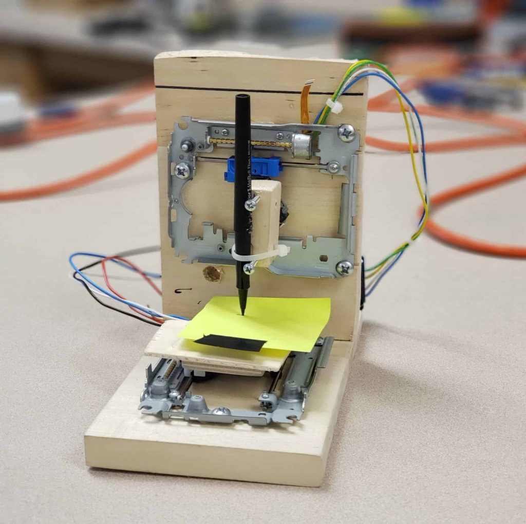
For my final milestone, I mounted a pen to the vertical stepper rail, and uploaded gcode through my computer to make it draw images. First, I had to upload some Arduino code that defined the controls that moves the motors. I then used a program called Processing to run a framework that allows gcode to be uploaded and ran using the previously defined controls. The only area I had problems with while accomplishing this milestone was coding. Figuring out the whole process for uploading gcode to my arduino was very confusing and there were no clear instructions on the internet, so I had to resort to other methods. First of all, I had to find the code to run. After some searching, I found that on another BlueStamp student’s blog. Figuring out how to run it was much more difficult. I eventually found out that I had to use Processing, which simplifies the process by a lot. After going through this whole process, I found out that the gcode that I had wasn’t working, so I had to figure out how to make my own gcode, which was also mind-numbingly hard. During this milestone, I learned how to make my own gcode, and how to upload that gcode to an arduino.
SECOND MILESTONE
For my second milestone, I screwed together two pieces of wood in an L shape, and attached my two stepper rails to them. To attach them, I had to make holes in the wood for the screws using a drill, and I screwed in those screws using an impact driver. I ran into a lot of problems while achieving this milestone, some of which I still have to fix. For starters, while drilling a hole into one of the stepper rails for a screw, I bent a part of the stepper motor and it became unusable. I had to get a new DVD drive for its stepper rail and start from scratch, but that wasn’t so bad, as I’ve done it twice already. While screwing the two wood blocks together, I stripped a screw, so an instructor had to get it out using a drill. I then also stripped the replacement screw while trying to make it flat with the bottom, so it didn’t go in all the way, and as a result, the whole thing rocks on a table a little bit. During this milestone, I learned how to use a drill and impact driver, and how to make holes for screws in wood and metal. For my next milestone, I’m going to add a pen to the vertical stepper rail, and get it to draw pictures on paper using code.
FIRST MILESTONE
For my first milestone, I dismantled two DVD drives, took the stepper rails out of them, soldered wires onto their stepper motors, and attached those wires to a L293D motor shield on top of an Arduino Uno The stepper rails are responsible for all the moving parts of the CNC plotter, and hold the paper and pen for drawing. The Arduino Uno connects to a computer and runs code so that the stepper motor can move the paper/pen. The L293D motor shield is inserted into the Arduino Uno, and it is where the wires from the stepper rails are screwed in. A USB breakout board is used to supply power to the whole thing.
I ran into a few difficulties while achieving this milestone, mainly involving soldering. Soldering the wires onto the stepper motors was an essential step that I couldn’t mess up. Four wires had to be soldered onto four very small contact points on the stepper motor. If the contact points touched each other, the system would short circuit and not work, and I would likely have to replace it with another one. Some very precise soldering was required to make this work. With an instructor’s help, I managed to solder the wires onto the first one, although I did mess up a few times and my instructor had to step in and fix things. After learning from this experience, soldering wires onto the second stepper rail was much easier, and went much smoother. Another difficulty I encountered was trying to find code to test that the stepper motors worked. After much googling and searching, I managed to find this link which provided a library that had test code in it for stepper motors. I ran it and to my surprise, everything worked the first time.
My next milestone will be finishing all the physical construction required for this project, which is mounting both stepper rails to wood and adding a paper surface and pen to them. I’m also thinking about screwing the Arduino Uno/L293D motor shield combo onto the wood so it doesn’t float around.
STARTER PROJECT
For my starter project, I chose to do the MintyBoost battery charger. It supplies power from two 1.5V double A batteries contained in a battery holder to the USB port on the circuit board and the connected device. The majority of the components on the circuit board, like the boost converter chip, IC socket, ceramic capacitors, electrolytic capacitors, power inductor, and 3.3K resistor are used to transfer power from the batteries to the connected device. The rest of the components, which include the 75K 1% and 49.9K 1% resistors and diode, are used for less important tasks, like figuring out what type of charger is connected.
Overall, this project was a good way to practice my newly acquired soldering skills for my main project, learning how to properly document my work, and acclimating to the BlueStamp environment. I definitely learned a lot that will be useful for my main project.
The Building Process
Instructions for building the MintyBoost can be found here.
- First, I soldered in the resistors. The R5 Resistor came first, then the R2 and R4 resistors, and then the R1 and R3 resistors.
- After that came the ceramic capacitors, which went in the C1 and C2 slots.
- Then came the D1 Diode, which was the first polar component I had to solder in, so it had to be inserted into the circuit board in a certain way.
- I then soldered in the IC socket, which went directly over the R5 resistor. It had eight connections and fit neatly into the circuit board.
- After that, I soldered in the power inductor in the L1 slot and electrolytic capacitors in the C3 and C4 slots.
- I then soldered in the wires of the battery holder and inserted the boost converter chip into the IC socket.
- I then checked that the circuit board/battery holder wasn’t warming up, and it wasn’t, so I moved on to check that the proper voltage was surging through the circuit board.
- Everything was in order, so I finally soldered in the USB port.
- I had accidentally left the batteries in while I soldered the USB port on, so they got really hot, which was bad. I replaced them with new batteries and plugged in a charging cable and my bluetooth earbuds case to test if it was working. The charging indicator light came on, so everything worked perfectly.
I let the whole thing cool for a bit before swapping out the batteries for new ones and testing it.“IT’S A MIRACLE NOTHING EXPLODED.”
R5 Resistor: The stripes are in orange-orange-red color order, which indicates a 3.3K resistor. This resistor is used to improve the high current capability of the boost converter chip. Something to note about this resistor, and all resistors in general, is that they are non-polar, which means they can be inserted any way into the circuit board. You don’t have to worry about putting it in “backwards”.
R2 and R4 Resistors: These resistors have the pattern Violet Green Black Red Brown, which means that they are 75K 1% resistors. These resistors are used to figure out what kind of charger is connected.
R1 and R3 Resistors: These resistors have a Yellow White White Red Brown pattern, which indicates that they are 49.9K 1% resistors. These resistors serve the same purpose as the R2 and R4 Resistors, which is figuring out what kind of charger is connected. The only difference between these two are their size and their color pattern.
C1 and C2 Capacitors: These ceramic capacitors are also non-polar, so they can be placed into the circuit board in any orientation. The capacitor in the C1 slot is responsible for stabilizing the output voltage, and filters out high frequency noise so that the 5V output is nice and smooth. The C2 capacitor is used to stabilize the internal reference of the boost converter chip. This keeps the chip stable so that it will generate a voltage as precise as possible.
D1 Diode: This diode is used to ensure that energy is transferred from the batteries to USB port, and not the other way around. Diodes have a special property that allows current to flow only one way, and because of this, the diode has to be inserted in a certain way into the circuit board, and is not non-polar.
IC Socket: This socket protects the boost converter chip and ensures that the boost converter chip can be replaced. It is placed over the resistor in the R5 slot.
L1 Power Inductor: This component is used by the DC/DC converter chip to store and convert power from low voltages to high voltages. Inductors are just a coil of wire, so they have no polarity, and can be placed either way.
C3 and C4 Electrolytic Capacitors: The two electrolytic capacitors placed in the C3 and C4 slots help smooth both the input and output voltages, to keep them stable during the up-conversion. They are used for low frequency noise, and are often paired with a ceramic capacitor. Electrolytic capacitors are polarized and must be placed correctly or the circuit will not work. The longer wire is the positive one and must be placed in the positive hole in the circuit board, and the shorter one is meant for the negative hole.
Boost converter chip: This chip is responsible for upping the voltage in the system while lowering current. It is inserted into the IC Socket, and is not soldered on to the circuit board, so that it can be replaced.
Battery holder: Contains two double a batteries and supplies their power through red and black cables that are soldered onto the circuit board.
USB port: A USB-A charging cable can be inserted into this port and power can be drawn to the connected cable/device from the system.