Arduino Pong Game
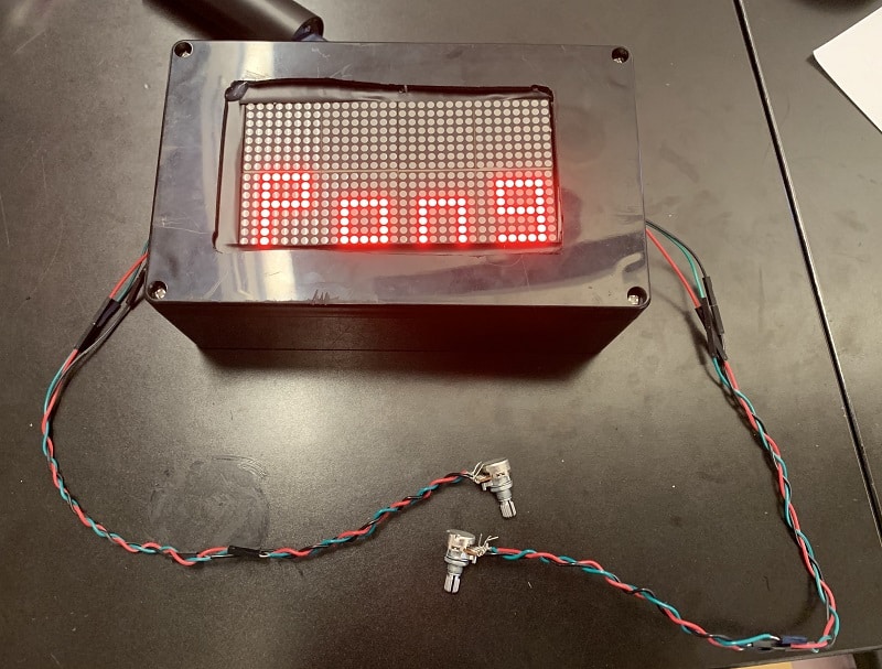
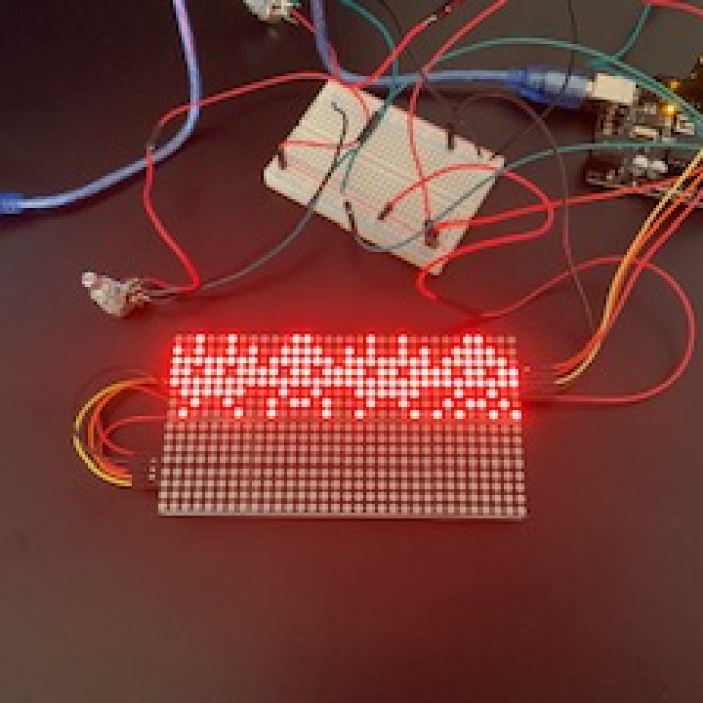
The LED matrices, powered by an Arduino, light up to show a game of Pong. The game can be played by turning the potentiometers to control the movement of the paddles.
| Engineer | School | Area of Interest | Grade |
|---|---|---|---|
|
Miriam R. |
HANC High school |
Art / Mechanical Engineering / Biology |
Incoming Junior |
REFLECTIONS
Before starting BlueStamp, I knew close to nothing about engineering. Now, through building my project, I learned how to use a dremel, drill, jigsaw, multimeter, and soldering iron. I also learned how to use an Arduino, breadboard, and potentiometers. I now know how to read the resistances of different resistors by looking at their bands, and I have a better understanding of programming. I overcame problems that came up during the process of making the game and I now have more confidence in dealing with issues that may come up in other projects I would create.
I really enjoyed making my project and I’m excited to take my new knowledge of engineering with me in the future.
FINAL MILESTONE
I finished my final milestone! To complete my project, I uploaded a program for a functioning pong game and set up the box for the display, Arduino, and breadboard to be in.
HOW IT WORKS
The code that I used set the display letters and numbers (ex: PONG, score, etc) as binary variables.
For example, the code below is to display the number 1 when showing the score.
					byte one[] = {
  B00111110,
  B00001000,
  B00001000,
  B00001000,
  B00001010,
  B00001100,
  B00001000,
  B00000000
};
To make it look as if the ball is moving around the display, the code used if and else statements.
For example, the code below keeps the ball moving in one direction:
					if (dirx == 1) {
  removeball(row, col);
  if (deflect == 0) {
    Row++; // Row = Row + 1;
    Col++; // Col = Col + 1;
    placeball(row, col);
    if (row == 15) { //if current row is 15 (the last) turn around
      deflect = 1; //
    }
    Return;
  }
This part of the code makes the ball switch directions when it hits a wall:
					 else {
    Row--; //row = row - 1
    Col++;
    placeball(row, col);
    diry = 1;
    deflect = 0;
    Return;
  }
The code is also set to read the values from the potentiometers and use that to control the paddles. The potentiometers work by changing the resistance depending on how the knob is turned.
This code reads the values and then converts them to an integer from 0 to 13 corresponding to the row of the bottom bit of the paddle:
					leftpongval = analogRead(leftpaddle);
leftpongval = map(leftpongval, 0, 1010, 0, 13);
rightpongval = analogRead(rightpaddle);
rightpongval = map(rightpongval, 1020, 20, 0, 13);
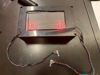
Once a player reaches five points, the score is reset to 0-0.
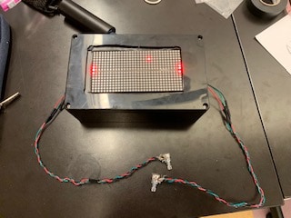
For the box, I cut a rectangle out of the top so the display can sit in and be seen. I used a drill to make holes at the corners of where I needed to cut and then I used a jigsaw to connect the holes and cut out the rectangle. I then needed to drill a small hole on both sides of the box for the wires connected to the potentiometers to come out of the box. This allows for the potentiometers to be turned and the game to be played. Lastly, I needed to drill three larger holes in a row and then file them until they were connected and were in a square shape. This hole is for the USB cord to connect to the power source.
I tried a couple of different tools to cut the top of the box. The first thing I tried was a dremel. The dremel was not good to use because it melted the plastic before it was able to cut through it. The next thing I tried was a hacksaw. I drilled the biggest size hole into each of the corners where I was planning to cut but when I tried to put the saw through the holes, they would not fit. I ended up needing to use a jigsaw to cut the holes. The second issue I had was after I cut the hole and tried putting the matrix threw it. The hole was too big. To fix this, I hot glued cardboard to the top of the box and cut out a smaller rectangle to perfectly fit the matrix.
FIRST MILESTONE
HOW IT WORKS
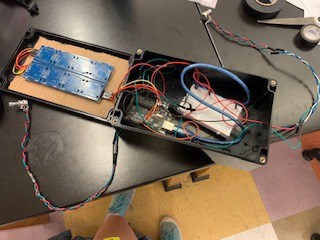
The matrices came with the breakout boards pre attached to each other in two rows of four. I hot glued the two rows together and used wires to connect the pins of the matrices to form the display board. Then I connected the other side of the matrix to the digital pins in the Arduino. I tested the display by uploading a test code to the Arduino. Next I had to wire the buzzer to the Arduino. Before I did that, I needed to solder a resistor onto the buzzer to so it would work properly. I tested it with a different code uploaded to the Arduino. Lastly, I needed to hook up the potentiometers to the Arduino. I soldered three wires onto the three ports on the potentiometers. One of them is for ground, one for 5V, and one for resistance. I used a breadboard for this step because I needed more ground and 5V ports. I found that the resistance of the potentiometer goes from 0 to 11k. I tested it by using a code for the potentiometer to control the beeping of the buzzer.
The first problem I had was when I first started and I didn’t understand anything about the matrices. I looked up a lot of tutorials so I would understand more about matrices and be able to set them up. I also learned more about how to use the Arduino. The second problem was that when I was testing the potentiometers they worked irregularly and the test code didn’t always upload properly. I found that switching the matrix’s ground and 5V wires from the Arduino to the breadboard made it work better.
Uploading all of the test codes and having to change them slightly to fit my circuit helped me understand more about coding. I also learned how to read the resistance of different resisters to find the right one. This and my better understanding about the LED matrix and Arduino will help me as I continue my project
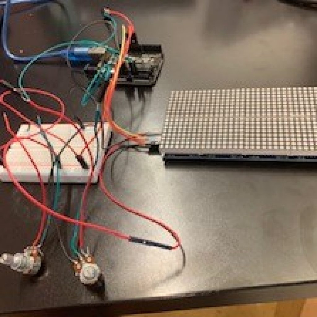
For my first milestone, I connected the two LED matrices together and then hooked it up to the Arduino. I also attached the buzzer and potentiometer to the Arduino and then tested everything.
STARTER PROJECT
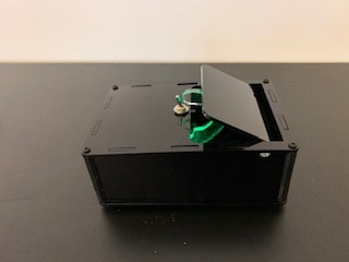
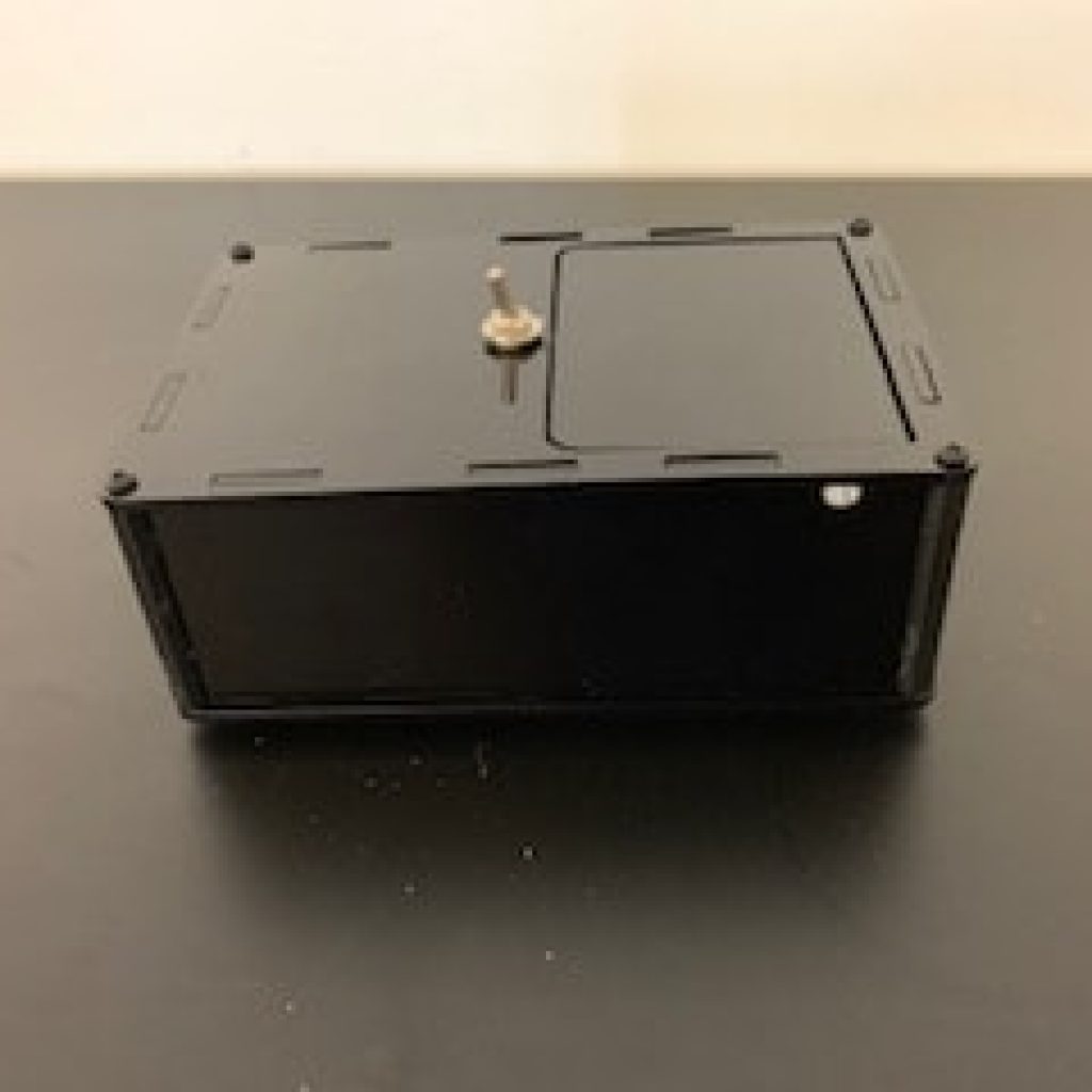
My Starter Project is the Useless Machine. It is a black box with a switch on top. When you flip the switch, a hook comes out of the box, pushes the switch back, and then the hook retracts back into the box. It essentially does nothing! I enjoyed building this project because I learned how to solder wires, that wires short circuit when they the cross, and how to use a drill.
The machine works by using a motor powered by batteries. When you flip the switch it rotates the motor which is attached to a hook. Once the hook comes up and flips the switch back, the direction of the motor is changed. When the hook comes parallel to the box, the back of it pushes down a kill switch to stop the motor until the switch is flipped again. There is also a light emitting diode (LED). A diode is an electrical component that only allows electricity to flow in one direction. An LED converts electrical energy into light. The LED turns on when the switch is flipped, changes color from red to green when it’s switched back, and turns off with the motor when the button is held.
The first problem I ran into occurred after I wired the control board and I tried to test it. Both the light and the motor were not working. Some of the wires were crossed and when I fixed that, the light started to work.To make the motor run, I had to resolder some of the ports. The last problem I ran into was when I tried to build the rest of the box around the circuit. The top wasn’t lined up correctly and therefore wasn’t able to click into place. I realized that it was off because the switch that I soldered in was crooked. Since I couldn’t fix that, I made the hole for the switch bigger by drilling it. I learned how to solder wires and that if wires cross each other, they will short circuit and not work. I also learned how to use a drill to make a hole bigger.
I’m now ready to bring all this knowledge into my main project.