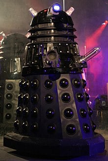
My project is an Emotive Robot, which, for fun, I designed to look like a Dalek from the BBC television programme “Doctor Who”. The robot is meant to react to proximity, and express a wide range of behavior sets, each one simulating a “mood”. The robot is more fun than practical, but maybe one day it could be used as the head for a race of therapeutic companion robots that eventually rise up and destroy humanity!
I learned a thing or two at Bluestamp. I taught myself how to use Fusion 360, and taught myself how to use the Arduino. The staff helped me debug my code, but I don’t know what I would have done if I didn’t have any prior knowledge. I built a Dalek, it was cool to see it come to life. I really enjoyed talking with the instructors, as they were really helpful, interesting, and fun. I am proud of my acomplishments here at Bluestamp, and look forward to building my own things in the future.
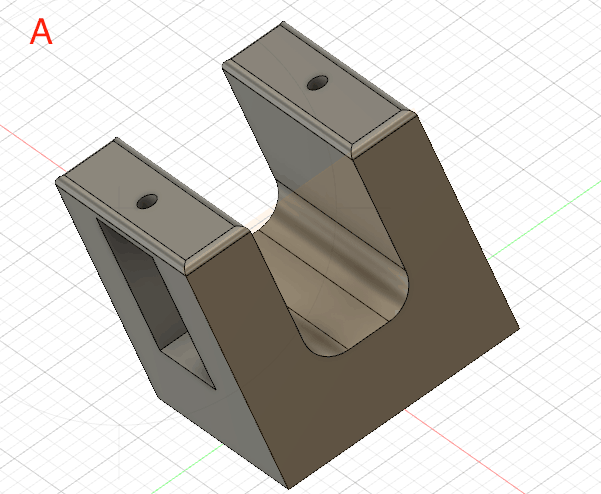
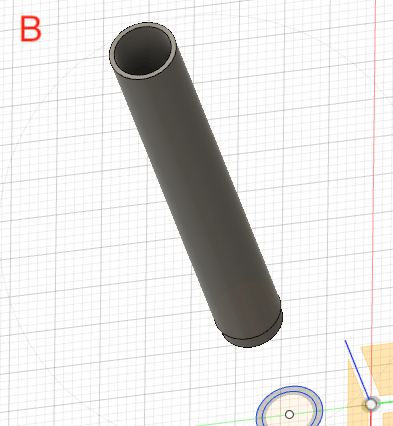
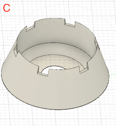
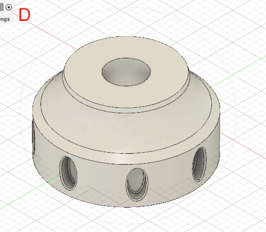
Model A: the custom head bracket. Model B: the Dalek’s stalk, connecting the eye to the body. Models C & D: the top and bottom halves of the eye respectively, split into two pieces for ease of printing.
Final Milestone
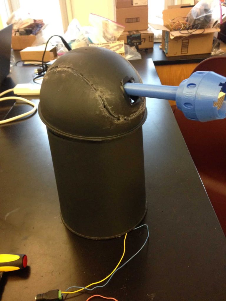
My final milestone was mostly cosmetic. I wanted to model the robot after the Daleks from my favourite show, “Doctor Who”. The body of a dalek is a pretty simple shape, so I used a trash can from umbra. The Daleks have an iconic eyestalk, which I 3D printed. To do this, I learned how to use Fusion 360. It took a night and some practice, but I was able to become pretty proficient with the software. I modeled the Dalek’s eye in two printable pieces (see models C and D) and the stalk (see model B), and then attached the printed versions to the trash can. Additionally, to keep the Dalek’s head stable, and attached to the servos, I 3D printed a custom bracket, special for my needed dimensions (see fig.1, and model A). I am really excited to use fusion 360 in the future. The trashcan came with a swing lid, so to make it more Dalek-esque, I used lots of hot glue and epoxy to seal the lid shut, then used a file to smooth it out. Finally, I used spray paint to further conceal the sealant. For the final part of this milestone, I attached the bracket and eyestalk to the servos mounted on the trash bin. The end reult was something that mildly resembled a Dalek (see fig. 2). I had a lot of fun this Milestone, and I look forward to modifications.
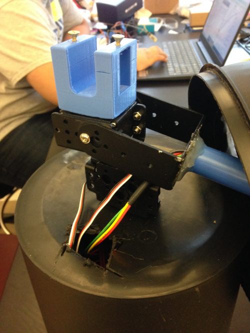
fig. 1: the 3D printed bracket used to stabilize the Dalek’s head, attached to the rest of the inside-the-head machinery.
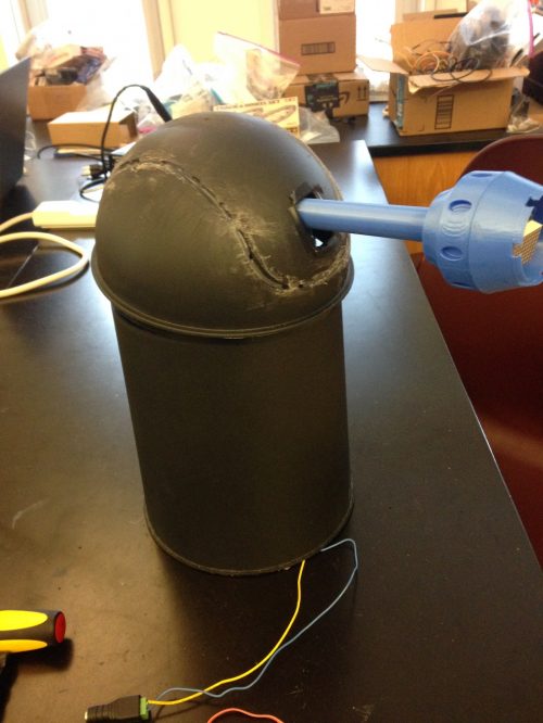
Fig.2: The end result, pre-spray paint
Model A: the custom head bracket. Model B: the Dalek’s stalk, connecting the eye to the body. Models C & D: the top and bottom halves of the eye respectively, split into two pieces for ease of printing.
Third Milestone
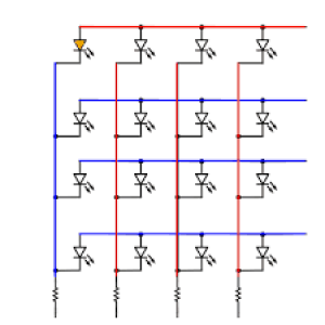
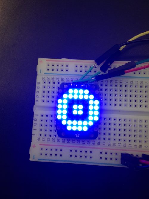
For Milestone 3, I assembled the final elements of my robot’s circuit, leaving it ready for fabrication in Milestone 4. The first step of this project was the wiring and programming of the LED matrix. This was pretty easy, as I had a website that programmed custom bitMaps for me. bitMaps are blocks of binary code that operate the LED matrix, a collection of LEDS arranged in an array. Using the website, I was able to make the LED matrix look like a Dalek eye (see fig. 1 below). Next came the hard part, the hardest in the project so far. The LED matrix refused to cooperate with both the servos and the speaker simultaneously. I could only ever get two of the three components to work together, as their libraries all called on the same parts of the Arduino. I eventually just used two Arduinos to get all three components functioning together. To be able to run the whole program from one machine, however, I made the second Arduino reliant for commands from the first, so that the first still controls and synchronizes everything. To do this, I programmed the original Arduino to send a signal to certain pins, instead of actually operating the matrix.
if(mood==2){ Serial.print(“chill”); servoschill(); exterminate(); digitalWrite(7,HIGH);//sends signal to Arduino 2 }}
On the other end of the wire, the second Arduino receives the signal, and is programmed to respond to that signal by operating the matrix (see wiring between Arduinos in fig. 2).
pinMode(11, INPUT); if (digitalRead(11) == HIGH) { eyemove(); }
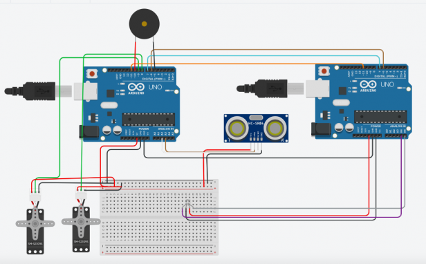
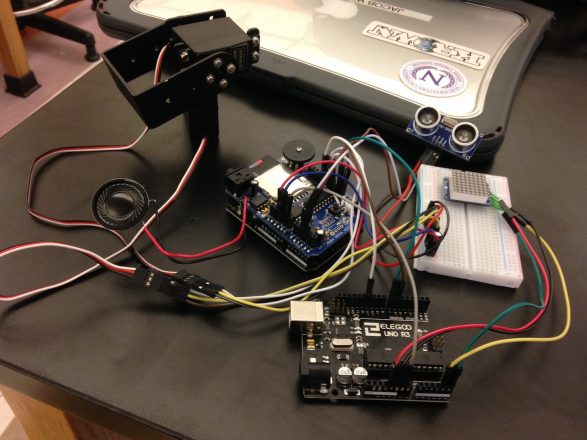
By having the two Arduinos interface in this manner, I was able to move on to integrating the Ultrasonic Sensor into the build. The final circuit design ended up a bit messy, but still worked (see fig. 3). I had some difficulty assembling components this milestone, but I am excited to move on to fabricating the Dalek.
Fig. 1: the matrix making a pattern reminiscent of an eye
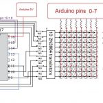
Fig. 2: the circuit design and wiring. Due to the limitations of the program, I was unable to display the WAV shield, Speaker, or LED matrix. I used a LED RGB to represent the matrix, located on the upper, mid-right part of the breadboard. It is wired as it would be if it were an LED matrix. The same can be said for the piezo, which is standing in for a speaker. The WAV shield is not displayed on the above image in any way, but it would be on top of the left Arduino, connected to the speaker.
Fig. 3: The completed circuit
SECOND MILESTONE
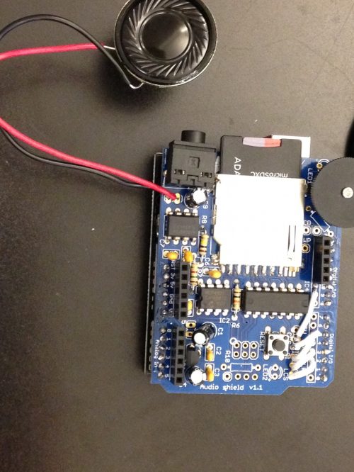
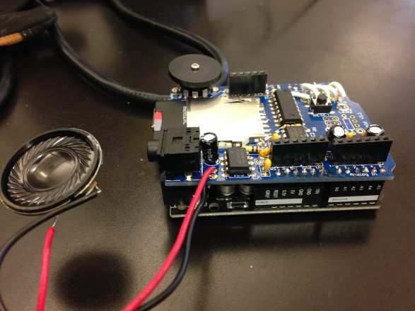
For milestone 2, I gave my robot the ability to speak. This was more difficult than my first milestone was, as it required more advanced programming, and some understanding of computer file structures. However, it still involved some soldering (see fig. 1). These were skills I really have not developed, so this milestone really helped me grow in my software skills. I am modeling my robot after the Daleks from Dr. Who, so I programmed the computer to say “exterminate”. Getting the Arduino to say this was a multi-step challenge. First, I had to solder my wave shield together, and then connect it to the Arduino underneath it (see fig. 2). I also had to learn about computer file systems through converting the mp3 sound effect to a WAV file. I then had to load the WAV of the Dalek saying exterminate onto my SD card, and from there, onto the WAV shield. I had very little experience with coding Arduinos to access files, so the coding was very difficult. Essentially, I had to add the contents of the SD card to the library of the program, then reference the contents individually, by name, using a play function.
					void loop(){

  play("EXTER.WAV", true);//play the file

}
The play loop that makes the Arduino speak.
Playing the sound file was more straightforward than the original code was, as can be seen in the final function of my code. A lot of the code is used to diagnose potential issues, and print the workings of the wave shield onto the serial monitor.
					void setup() {

  Serial.begin (9600); // prints warnings to help users diagnose the problem

  Serial.println("Initializing SD card...");

  if (!sdCard.init()) Serial.println ("Card could not be read");

  sdCard.partialBlockRead(true); //built in SD card function that allows the file to be read faster

  if (!volume.init(sdCard)) Serial.println ("Volume could not be opened");

  if (!fatRoot.openRoot(volume)) Serial.println ("Root could not be opened");

  Serial.println ("Card initialized");

}
As you can see, a large chunk of code was made to diagnose potential problems, and update users as to the workings of the SD card.
I learned a lot about software this milestone, and I look forward to combining this with milestone 1.
Fig 1. The wave shield and speaker as seen from above
Fig 2. The completed circuit vertically integrated with the Arduino
FIRST MILESTONE
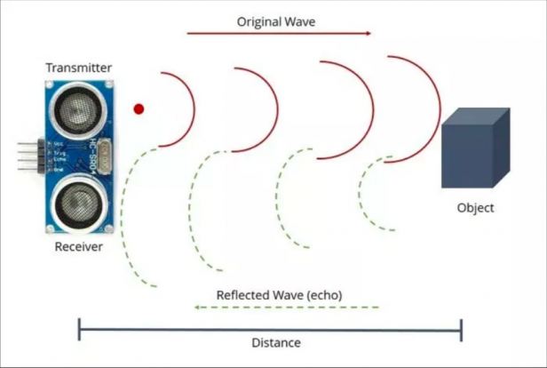
For Milestone one, I wired two servo motors and an ultrasonic sensor to my Arduino, and programmed the Arduino to respond to proximity by turning the servos. When the ultrasonic sensor detects an object in front of it within a certain radius, the servos whir back and forth. I had to learn how to operate servos through Arduino, but with the help of the code library, the process was rather straightforward (see code below). I also learned a bit about plugging components into the Arduino, such as learning how to use digital input/output pins. See declaration of pin outputs in the opening variables of my code below. The sensor has two functional pins, the trigger pin, and the echo pin (trigPin and echoPin). The trigPin sends out the sound wave, and the echoPin receives the sonic wave, when it bounces back to the sensor, off an object (See figure 1). This is controlled in the first commands of the loop. See code below for details.
HOW IT WORKS
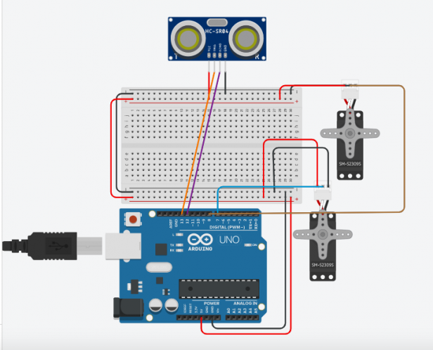
The emitter on the ultrasonic sensor fires out high-frequency sound waves. The sound waves bounce off objects in front of the sensor, and are deflected back to the sensor. When the sensor detects a sound wave, the sensor measures the distance between the object and, based on the qualities of the returning sound waves. Below in figure 1 is a diagram displaying the way Ultrasonic sensors work. I programmed the Arduino to start rotating the servos whenever the distance between an object and the ultrasonic sensor is measured as smaller than 20. Attached is a diagram displaying the wiring I used.
Fig. 1: diagram depicting the way an ultrasonic sensor functions randomnerdtutorials.com
Fig. 2 :Circuit diagram displaying the wiring between the servos, Arduino, and US sensor
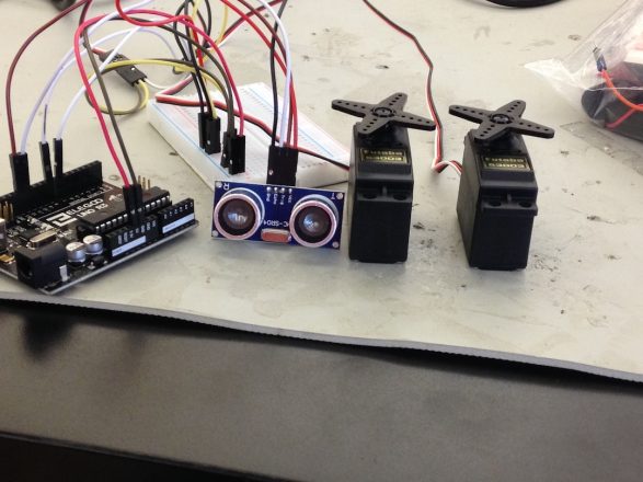
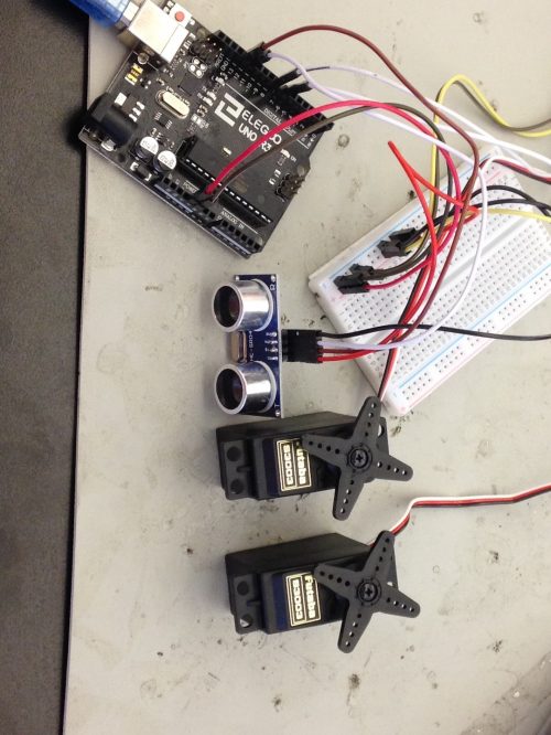
fig. 3: View of the circuit from the front
fig. 4: Top-down view of the circuit
STARTER PROJECT
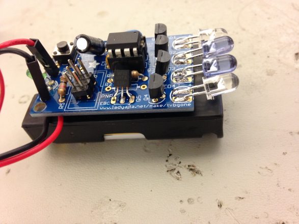
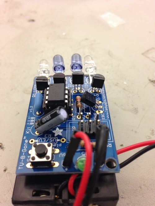
For my starter project, I made a TV-B-gone machine, essentially a universal remote that sends infrared (IR) waves in the direction it is pointed. IR waves are a variety of wavelengths invisible to the human eye, but visible to specialized computer sensors. The flashing pattern of the IR LEDs (Light Emitting Diode) tells most televisions to shut off. An LED is a special electronic component that creates light when a current is run through it. The different types of IR LEDs mean that the device can communicate on a wide range of frequencies. The project is powered by two AA batteries, and several components, such as capacitors, resistors, and five transistors. These parts serve to restrict, direct, and smooth out the current flow throughout the circuit, essentially making sure that the right amount of energy gets from the battery to the LEDS (see row of black pieces on the right side of the circuit, fig.1). The circuit has five of these LEDS, four of which are infrared (see fig. 2). The human eye cannot see infrared, so there is an extra, green LED, so that the naked eye can see if the device is functioning. The circuit is activated at the press of a button, which lets power into the circuit which the computer directs the LEDS to flash, via the transistors. The whole machine is mounted on a PCB, a printable circuit board. The gadget is primarily useful as a prank, but doesn’t have much practicality outside of that. The tv-b-gone works by broadcasting IR beams on a variety of wavelengths, sending out bursts in a hit-or-miss style signal to a television’s receiver, telling the TV to turn off.
Fig. 1: Side view of the TV-B-Gone
Fig. 2: The TV-B-Gone, as seen from above
STAY CONNECTED TO BLUESTAMP
The BlueStamp Engineering Website is set to allow the use of cookies. Cookies help us to give you the best experience on our website. By clicking Accept or continuing to use the site, you agree to use our cookies. If you decline we will not track your information but your browsing experience might be limited. For more information on our Privacy Policy click here.