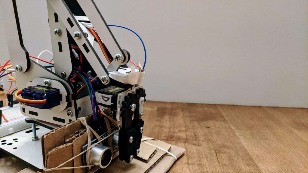
Autonomous Pick and Place Robotic Arm
This is an autonomous pick and place robotic arm based on ultrasonic sensors.
| Engineer | School | Area of Interest | Grade |
|---|---|---|---|
|
Clarissa L. |
Lynbrook High School |
Computer Science |
Rising Junior |
REFLECTION
There is so much more to engineering than software. I have had a wonderful three weeks exploring robotics, and it has been a great learning experience. Bluestamp has inspired me to expand on my Arduino knowledge and possibly try Raspberry Pi while working on more projects in the future.
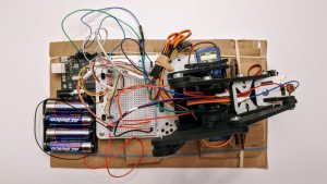
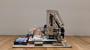
BILL OF MATERIALS
1 ArmUno 2.0 Robotic Arm Kit
1 Arduino Uno
1 4 x AAA Battery Mount
4 SG90 Servos
1 HC-SR04 Ultrasonic Distance Sensor
1 Laser Diode
13 Male-to-Male Jumper Wires
4 Male-to-Female Jumper Wires
DEMO NIGHT PRESENTATION
MILESTONE THREE
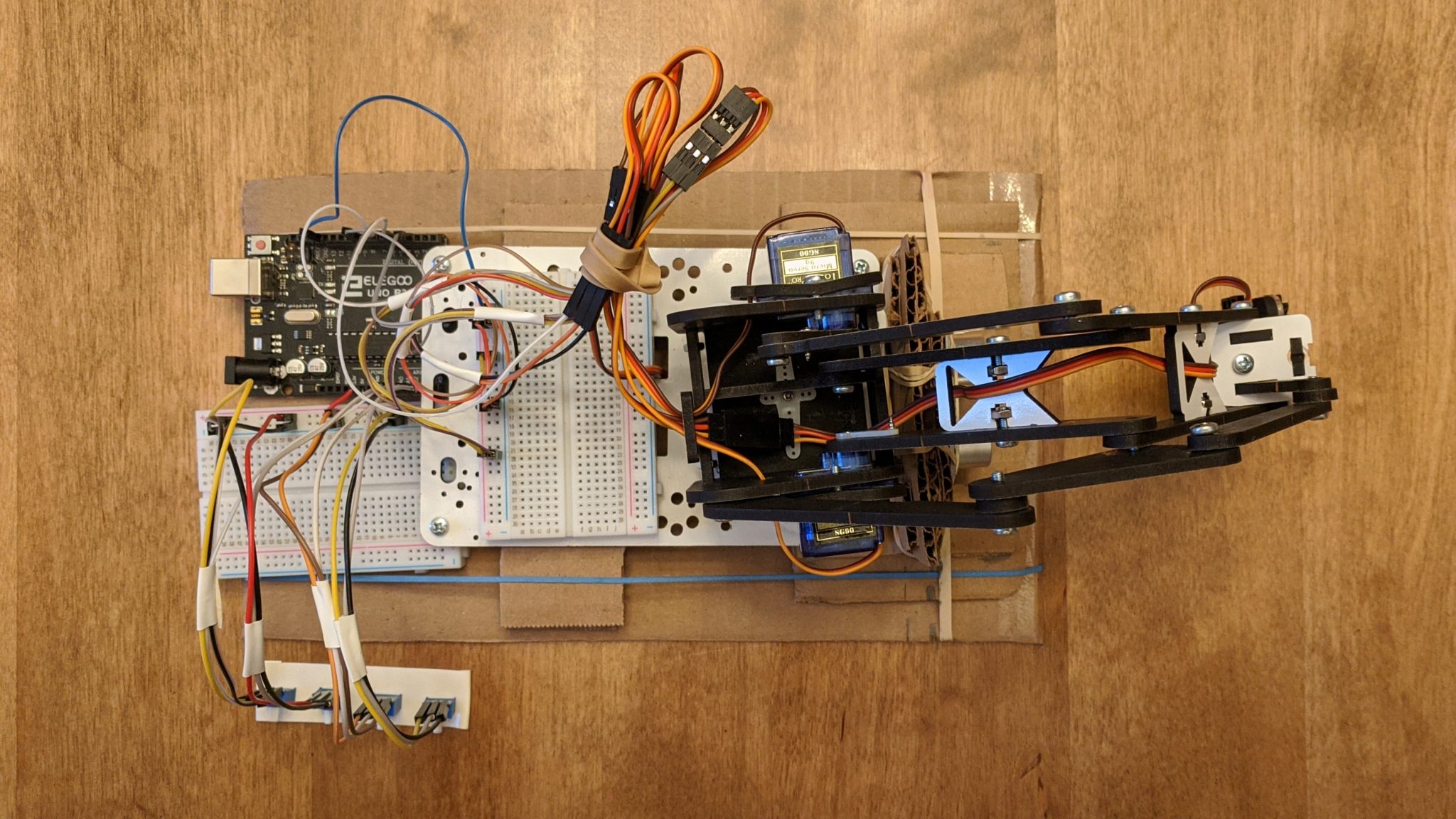
Here’s a short video about my third milestone! I have finally added the distance sensor, and the arm is fully operational.
ADDITIONAL PROJECT COMPONENTS
1 HC-SR04 Ultrasonic Distance Sensor
1 Laser Diode
2 Additional Male-to-Male Jumper Wires
4 Additional Male-to-Female Jumper Wires
UNDERSTANDING ADDITIONAL PROJECT COMPONENTS
HC-SR04 Ultrasonic Distance Sensor
This sensor uses ultrasonic signals to measure distance. To get a distance, first, send a pulse of HIGH for 10 microseconds over the TRIG pin. This will send eight 40 kHz ultrasonic signals through the transmitter. The receiver will start a clock and wait for the sound waves to be reflected. If there is an object within 2 to 400 centimeters of the sensor, the object will reflect the sound waves to the receiver mounted on the sensor. The user can then take the duration it took for the sound waves to be returned to the receiver and calculate the distance of the object from the sensor using the distance formula and the speed of sound.
You can use the NewPing library to use the HC-SR04. The NewPing library makes controlling one or more ultrasonic sensors easy, and it is also better than writing the code from scratch using pulseIn() because pulseIn() tends to be inaccurate for some ultrasonic sensors.
When running the sensor, you may notice that the distance output is inaccurate. This may be due to the speed of sound. Ultrasonic signals travel at the speed of sound, but the speed of sound is not immutable. It can be affected by medium, temperature, and humidity. You can attach a temperature and humidity sensor, such as the TCH-11 or TCH-22, to factor in the current temperature and humidity into your distance calculations. Unfortunately, this also has its downfalls. The reason I did not include a TCH-22 into this project is due to the stabilization time. It takes roughly five seconds for the sensor to stabilize, but factoring the robotic arm, the lag this delay would cause is not worth the slightly improved accuracy.
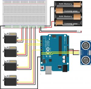
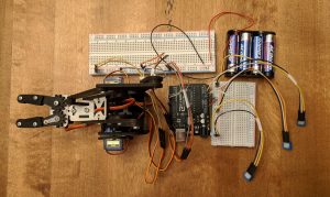
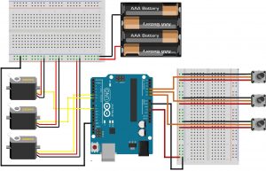
This is the updated circuit diagram. All potentiometers are removed. One HC-SR04 and one laser diode has been added to the circuit.
See Milestone One Circuit Diagram section for common mistakes made when wiring the circuit.
					// For Platform.io, must import Arduino, Servo, and NewPing libraries.
// If using Arduino IDE, only need to import Servo and NewPing libraries.
#include <Arduino.h>
#include <Servo.h>
#include <NewPing.h>

// Constants for HC-SR04.
#define TRIGGER_PIN 11 // Input pin for HC-SR04
#define ECHO_PIN 12    // Output pin for HC-SR04
#define MIN_DIST 3     // Closest distance the arm can reach
#define MAX_DIST 12    // Farthest distance the arm can reach

// Create servo objects.
Servo servoA; // Arm Servo: Moves arm forwards and backwards.
Servo servoB; // Base Servo: Moves entire arm left and right.
Servo servoC; // Arm Servo: Moves arm up and down.
Servo servoD; // Claw Servo: Open and closes the claw.

// Create NewPing object.
NewPing sonar(TRIGGER_PIN, ECHO_PIN, MAX_DIST);
int distance; // Used in loop().
int angleA, angleC;

// Angles for servoA and servoC.
int tableA[10] = {118, 132, 126, 134, 131, 144, 156, 156, 179, 179}; // <distance, angleA>
int tableC[10] = {139, 124, 148, 139, 157, 164, 168, 168, 180, 180}; // <distance, angleC>

void resetArm()
{
  // Arm resting position.
  servoA.write(90);
  servoB.write(90);
  servoC.write(180);
  servoD.write(90);
}

void setup()
{
  // Servos attached to corresponding PWM pins.
  servoA.attach(9);
  servoB.attach(6);
  servoC.attach(5);
  servoD.attach(3);

  resetArm();
}

void grabItem()
{
  servoD.write(180);
  delay(1000);
  servoA.write(angleA);
  delay(1000);
  servoC.write(angleC);
  delay(1000);
  servoD.write(110);
  delay(1000);
}

void dropItem()
{
  servoB.write(180);
  delay(1000);
  servoD.write(180);
  delay(1000);
}

void loop()
{
  distance = sonar.ping_cm(); //TODO implement mode/median

  if (distance < MIN_DIST || distance > MAX_DIST)
  {
    return; // Outside of arm reach range, quit loop for this iteration.
  }

  distance -= 3; // Transpose distance value to array index value.

  angleA = tableA[distance]; // Get angle data from array.
  angleC = tableC[distance]; // Get angle data from array.

  grabItem(); // Grabs item.

  resetArm(); // Brings arm back to resting position.
  delay(1000);

  dropItem(); // Drops item to left of arm.
  resetArm(); // Brings arm back to resting position.
}
The above code uses input from a distance sensor to autonomously grab an item and move it with the robotic arm.
MILESTONE TWO
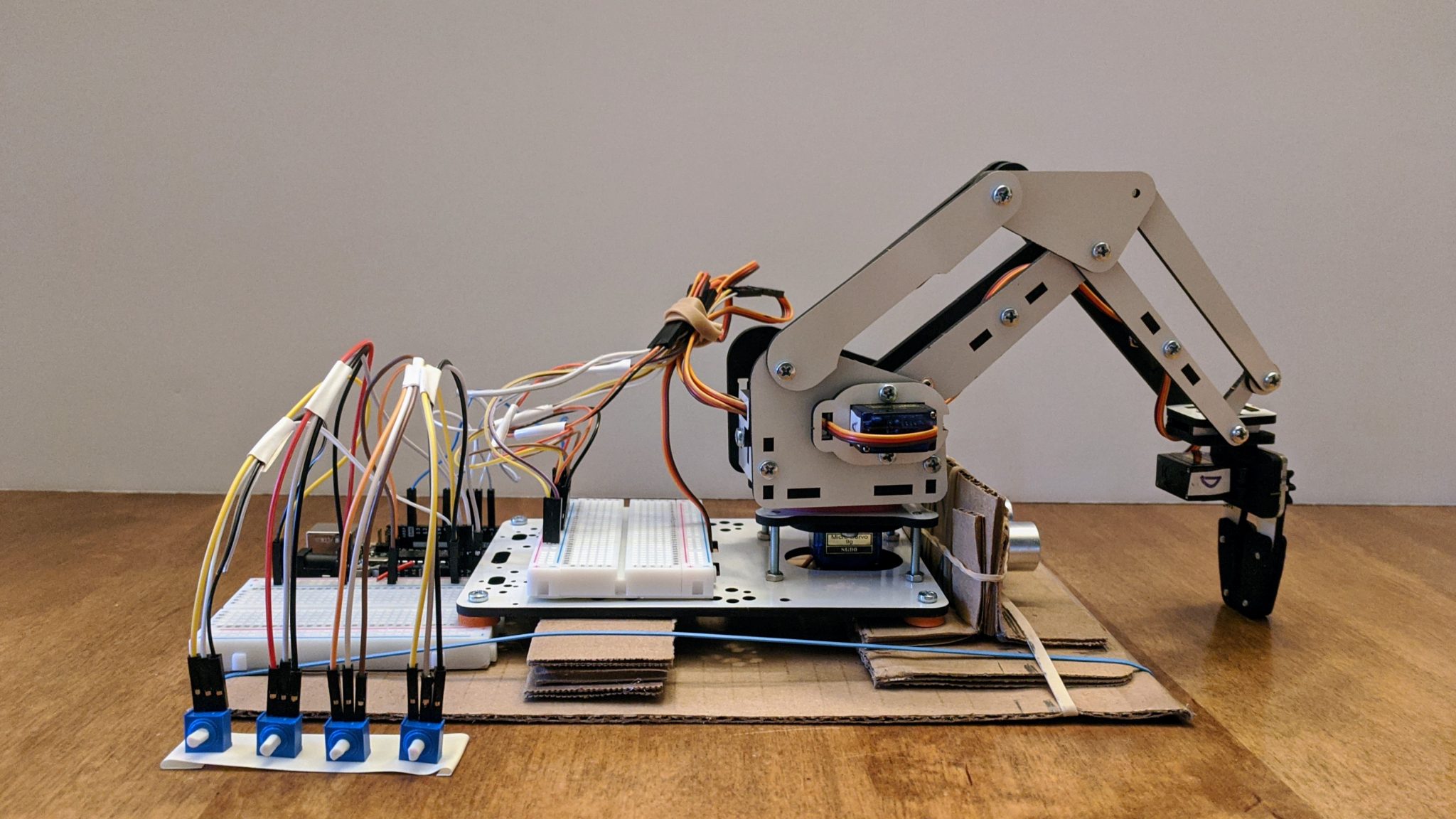
Here’s a short video about my second milestone! So far, I have added the last servo and corresponding potentiometer.
You may notice that in the video that the arm sometimes moves sporadically even when I am not turning the potentiometers. This is not a coding or wiring issue. Rather, the potentiometers are cheap and can output unstable values if the wires connecting them to the Arduino are disturbed even slightly. Fortunately, potentiometers are only a temporary controller, so this will not be a major issue in the long run.
ADDITIONAL PROJECT COMPONENTS
1 Additional SG90 Servo
1 Additional Potentiometer
3 Additional Male-to-Male Jumper Wires
3 Additional Male-to-Female Jumper Wires
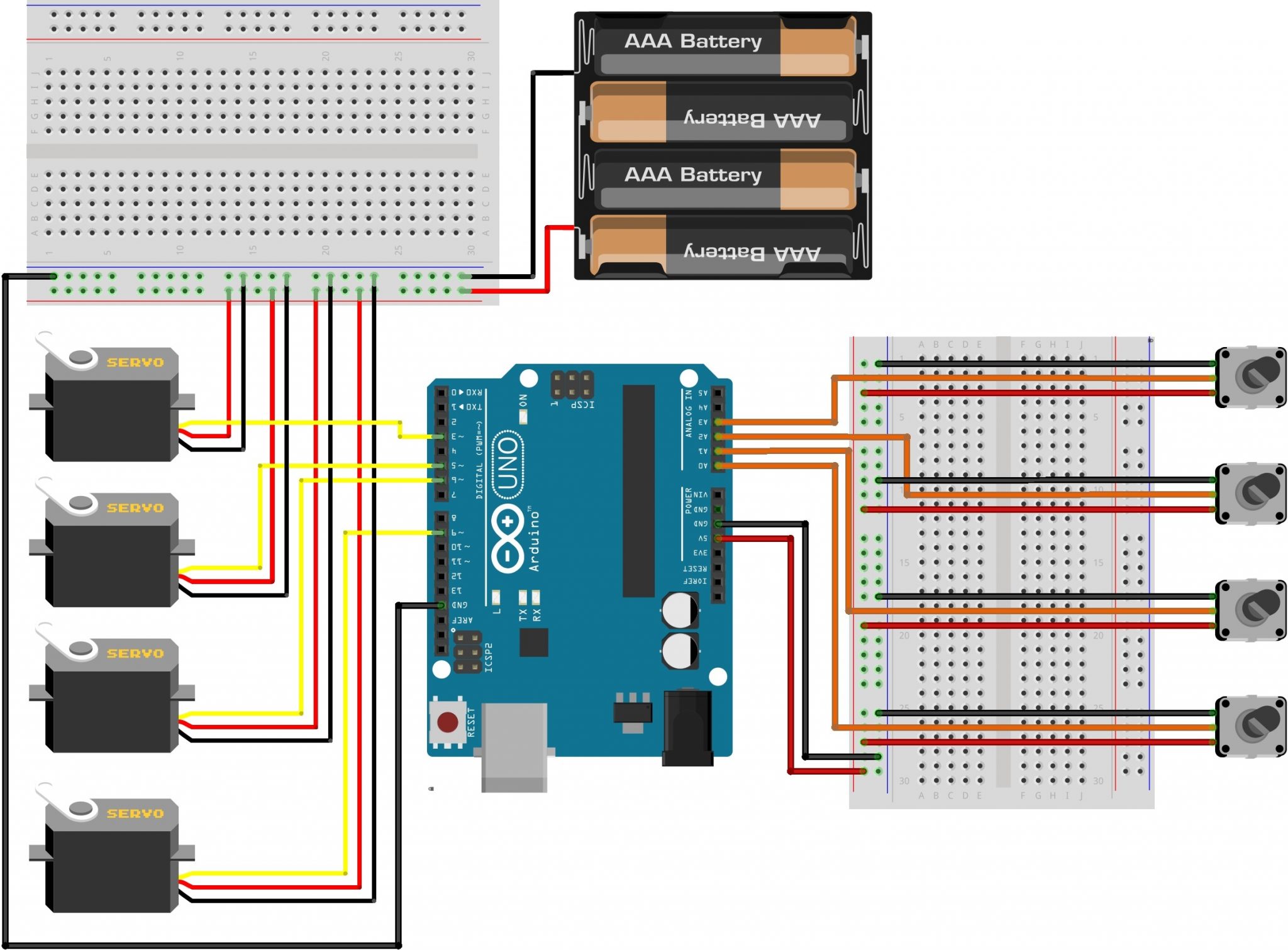
This is the updated circuit diagram. One servo and one potentiometer has been added to the circuit. Four potentiometers are connected to four servos through the Arduino, and each potentiometer controls one servo.
See Milestone One Circuit Diagram section for common mistakes made when wiring the circuit.
The above code takes input values from four potentiometers and outputs those values to four servos.
Note that servoC’s input range has been changed from 0 to 180 degrees to 90 to 180 degrees to prevent servo coordination issues between itself and servoA, which both control the arm.
					// For Platform.io, must import Arduino and Servo libraries.
// If using Arduino IDE, only need to import Servo library.
#include <Arduino.h>
#include <Servo.h>

// Analog input pins for potentiometers.
#define POTA A0 // For servoA.
#define POTB A1 // For servoB.
#define POTC A2 // For servoC.
#define POTD A3 // For servoD.

// Create servo objects.
Servo servoA; // Arm Servo: Moves arm forwards and backwards.
Servo servoB; // Base Servo: Moves entire arm left and right.
Servo servoC; // Arm Servo: Moves arm up and down.
Servo servoD; // Claw Servo: Open and closes the claw.

void setup() {
  // Set potentiometer pins to INPUT mode to receive
  // analog values.
  pinMode(POTA, INPUT);
  pinMode(POTB, INPUT);
  pinMode(POTC, INPUT);
  pinMode(POTD, INPUT);

  // Servos attached to corresponding PWM pins.
  servoA.attach(9);
  servoB.attach(6);
  servoC.attach(5);
  servoD.attach(3);
}

void loop() {
  // Read value from potentiomter. Servos can only take
  // value from 0 to 180 degrees, so must map analog
  // range 0 to 1023 to range 0 to 180.
  int stateA = map(analogRead(POTA), 0, 1023, 0, 180);
  int stateB = map(analogRead(POTB), 0, 1023, 0, 180);
  int stateC = map(analogRead(POTC), 0, 1023, 90, 180); // Arm movement for servoC limited to 90+ degrees due to arm construction.
  int stateD = map(analogRead(POTD), 0, 1023, 90, 180); // Arm movement for servoD limited to 90+ degrees due to arm construction.

  // Write mapped potentiometer values to corresponding servos.
  servoA.write(stateA);
  servoB.write(stateB);
  servoC.write(stateC);
  servoD.write(stateD);

  // No need to loop over loop() so fast. Delay slows it down.
  delay(50);
}
MILESTONE ONE
Here’s a short video about my first milestone! So far, I have completed the arm construction and hooked up a temporary controller using potentiometers.
PROJECT COMPONENTS
1 ArmUno 2.0 Robotic Arm Kit
1 Arduino Uno
1 4 x AA Battery Mount
3 SG90 Servos
3 Potentiometers
2 Solderless Breadboards
12 Male-to-Male Jumper Wires
9 Male-to-Female Jumper Wires
UNDERSTANDING PROJECT COMPONENTS
4 x AA Battery Mount
SG90s usually run on a voltage input from 4 to 6 volts. Four AA batteries or AAA batteries will provide you with 6 volts in addition to an adequate current to run three servos.
Avoid using 9-volt batteries if possible since the high voltage is likely to short the servos. These batteries also tend to produce less current than four AA or AAA batteries, so the servos may not even be powered. You can check the voltage input into your servos with a multimeter. If you do not have AA or AAA batteries on hand, adding two 9-volt batteries in parallel to your circuit should provide enough current for the servos to run.
Servos and Pulse Width Modulation
Servos internally use DC motors along with a potentiometer to rotate to a certain angle with greater accuracy and precision. Excluding continuous rotation servos, servo rotation is usually limited between 0 to 180 degrees. Servos use a three-wire system: one for ground, one for VCC, and one for control.
The control wire takes input in the form of pulse width modulation (PWM). The Arduino Uno has six PWM pins, which are digital pins capable of pulse width modulation. You can connect the control wire from the servo to any of these six. A servo can receive angle values from the PWM pin and rotate to the given angle.
PWM is a way to digitally encode an analog signal. A digital signal has a finite number of values while an analog signal can have infinite values. In this case, a digital pin can output one of two values: HIGH or LOW. Let’s say the HIGH value is 5 volts and the LOW value if 0 volts. Using a duty cycle, the percentage of the time the digital signal is HIGH, output values that are not 0 volts or 5 volts can be produced from a PWM pin. For example, with a duty cycle of 50%, the output will be 2.5 volts since the pin is only HIGH half the time.
Arm Assembly Note Concerning Servos: The ArmUno assembly instructions do not mention this, but it is extremely helpful to calibrate your servos before use. Calibrating servos is essentially setting them to the same angle, so when you attach arms to it, it is easier to determine their full range of motion.
Potentiometers
A potentiometer is a variable resistor. Like a servo, it uses the three-wire system: one for ground, one for VCC, and one for control. When connected to an Arduino Uno, it can output an analog value. Since an Arduino Uno has a 10-bit analog to digital converter, a potentiometer connected to an Arduino Uno can return a value from 0 to 1023. This is because a bit has two states: on or off. With 10 bits, 2 to the 10 different integer values can be stored. 2 to the 10 is 1024, but since 0 is included, the range of integer values will be from 0 to 2 to the 10 – 1 or 0 to 1023. To output values, a potentiometer requires power. These potentiometers require between 3.3 and 5 volts though 5 volts tends to be more stable; you can use either of Arduino’s 5 volt or 3.3 volt pins or an external power source to power your potentiometers.
This is the circuit diagram. Three potentiometers are connected to three servos through the Arduino, and each potentiometer controls one servo.
Common Mistakes
Servos require 4 to 6 volts; you should use an external power source since the Arduino VCC pins do not produce enough current to drive motors. Your servos may not run if they do not receive enough current. Use a multimeter to check the voltage input for servos that do not seem to be receiving any power.
Servo control wires must be connected to digital pins capable of pulse width modulation.
Potentiometer control wires must be connected to analog pins.
A common ground must be set between the Arduino board and the battery pack. Your circuit will not be stable if you fail to do this, which may cause unpredictable potentiometer outputs.
					// For Platform.io, must import Arduino and Servo libraries.
// If using Arduino IDE, only need to import Servo library.
#include <Arduino.h>
#include <Servo.h>

// Analog input pins for potentiometers.
#define POTA A0 // For servoA.
#define POTB A1 // For servoB.
#define POTC A2 // For servoC.

// Create servo objects.
Servo servoA; // Arm Servo: Moves arm forwards and backwards.
Servo servoB; // Arm Servo: Moves arm up and down.
Servo servoC; // Claw Servo: Open and closes the claw.

void setup() {
  // Set potentiometer pins to INPUT mode to receive
  // analog values.
  pinMode(POTA, INPUT);
  pinMode(POTB, INPUT);
  pinMode(POTC, INPUT);

  // Servos attached to corresponding PWM pins.
  servoA.attach(9);
  servoB.attach(6);
  servoC.attach(5);
}

void loop() {
  // Read value from potentiomter. Servos can only take
  // value from 0 to 180 degrees, so must map analog
  // range 0 to 1023 to range 0 to 180.
  int stateA = map(analogRead(POTA), 0, 1023, 0, 180);
  int stateB = map(analogRead(POTB), 0, 1023, 0, 180);
  int stateC = map(analogRead(POTC), 0, 1023, 90, 180); // Arm movement for servoC limited to 90+ degrees due to arm construction.

  // Write mapped potentiometer values to corresponding servos.
  servoA.write(stateA);
  servoB.write(stateB);
  servoC.write(stateC);

  // No need to loop over loop() so fast. Delay slows it down.
  delay(50);
}
The above code takes input values from three potentiometers and outputs those values to three servos.