RC Hovercraft
An RC Hovercraft is a remote controlled vehicle that can move on both water and ground. It lifts off the ground using a centralized motor and moves forward and side to side using another motor and a servo. The skirt below the hovercraft fills with air and allows the hovercraft to freely move on water and other surfaces.
| Engineer | School | Area of Interest | Grade |
|---|---|---|---|
|
Oscar C. |
The King’s Academy |
Mechanical Engineering and Quantum Physics |
Rising Senior |
THIRD MILESTONE
Brief Introduction
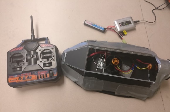
For my third and final milestone, I completed the aesthetics for my hovercraft as well as attaching the servo on my hovercraft. I also troubleshot a lot, as the skirt had many issues. I made many adjustments to the skirt, as well as figuring out how to attach the servo properly to the back of the hovercraft without compromising the balance of the hovercraft.
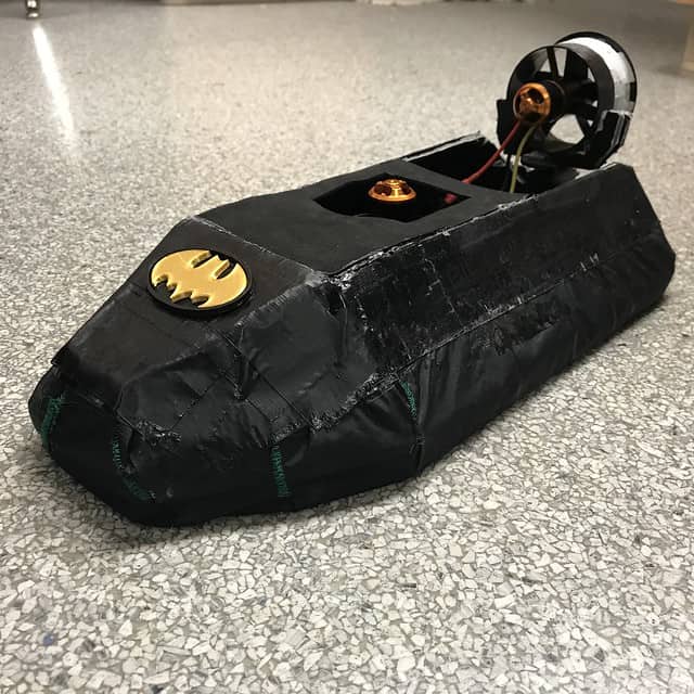
Figuring out how and where to attach the servo was difficult since the back of my hovercraft didn’t have much space left after inserting the mounting for the thrust motor. What I decided to do is cut out a slot in the mounting depron for the servo, and I just hot glued the servo into the slot. I then attached the motor onto the servo, by putting the motor on a mounting shaped depron then hot gluing both the depron and the motor. Then I had a problem with the skirt. After attaching the servo on the hovercraft, the hovercraft tended to flip over a lot when I turned the hovercraft. I was able to fix that problem by tightening up the skirt. I just removed the duct tape holding the skirt, and then I tightened up the skirt and duct taped it again. That allowed the hovercraft to hover much closer to the ground. I also had to poke a lot of large holes at the bottom of the hovercraft, so that it would move much smoother when moving. For the aesthetics, I just spraypainted the hovercraft black as well as putting a covering over the top of my hovercraft. I also added a batman sign on the front of the hovercraft. For my struggles, I had problems with the servo as well as the skirt. I took a long time trying to figure out the servo and skirt, but eventually, I figured it out and it worked. I learned that spraypaint somewhat ruins the adhesive of duct tape, so I will refrain from spraypainting duct tape in the future.
SECOND MILESTONE
Depron is a closed polystyrene sheet. It is light and moisture resistant and is rigid enough to provide a solid structure for my build. The entire frame of my build is made up of depron. It will also assist with keeping the electronics dry if I do decide to drive the hovercraft on water. I used hot glue to keep all the depron pieces together and to make sure that they wouldn’t shift around when the hovercraft was moving. Hot glue also acts as a seal for the hovercraft, as it can prevent many materials/substances such as water or gravel from entering small crevices in the hovercraft. The stitching and tent fabric were used to make the skirt. The stitching was made with a sewing machine, and it makes sure that the skirt was as airtight as it could be, as well as making the fabric a better fit for the frame of the hovercraft. The skirt is responsible for holding the air for the hovercraft, and allows the hovercraft to essentially “float”. The duct tape was used to hold the skirt to the frame. It is used as a temporary way to attach the skirt to the frame of the hovercraft, as I will later exchange this duct tape for either hot glue or super glue. I used duct tape since it is easy to remove and it allows me to test the hovercraft without adding anything permanent. Some difficulties I had was with the frame and the stitching. The frame required a few pieces of depron that were difficult to cut out, so it took some time to get a few of those pieces in. I was also new to stitching, and it was difficult to figure out how to use the sewing machine at first. The main thing I learned in this milestone was how to sew.
For my second milestone, I completed the frame and skirt of the hovercraft, and I inserted the wiring into the main build. This way, I am able to test if the hovercraft works and what I can adjust. The main parts of the frame and the skirt are the depron boards, the hot glue, stitching, and duct tape. For my next milestone, I will be testing and troubleshooting the hovercraft and improving the build of the hovercraft. I will also try and figure out a way to attach the servo.
FIRST MILESTONE
The receiver receives information about what position the lever is in on the controller. After the information is received, the receiver sends that information to the ESC, which then takes that information and adjusts the speed of the motor based on the orientation of the lever. One of the motors is responsible for providing lift, while the other motor is responsible for providing thrust for the hovercraft. The controller and receiver work together to manage the speed of the motors. The servo is used to turn the hovercraft. Some difficulties I had this milestone was trying to connect the motor to the ESCs. The connectors used to connect the motors the ESCs were not part of the motor, and I had to solder them onto the motor in order to connect the motors the ESCs. The connector design was very weird as well, so it was very difficult to solder together. Another thing I had trouble with was the channels on the controller and the receiver. I had no idea which channel corresponded to which lever on the controller, so it took a while to figure that out. I learned a lot about electricity and wiring in this milestone, as one of my mentors took a lot of time explaining electricity and wiring to me to help me figure out how to wire everything.
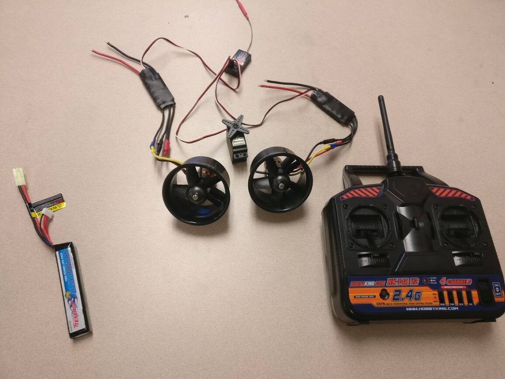
For my first milestone, I completed all the wiring for the hovercraft. The wiring connects the motors and the servo to the receiver so that the controller can control which direction the hovercraft goes. The main components of the wiring are the motors, the ESCs, the servo, the receiver, the controller, and the battery.
STARTER PROJECT: USELESS MACHINE
The lever sends a signal to the arm and allows the arm to move. The snap switch is triggered once the arm moves back to its starting position, stopping the arm from moving any further than it needs. The motor controls the arm by turning gear shafts inside the motor which in turn moves the servo attached to the end of the motor which then moves the arm. The arm is attached to the servo and is responsible for moving up and hitting the switch when the lever is flipped. The PCB distributes electricity to the entire system and is where most of the other components are attached. The battery pack provides power to the PCB which in turn powers the machine. The LED lights up whenever the lever is flipped and works with the resistors in order to produce the correct color of light when the lever is flipped. Inside the lightbulb, there are two LEDs, and the resistors make sure that only one LED lights up at a time when the lever is flipped. If the resistors were not there, both LEDs would light up at the same time.
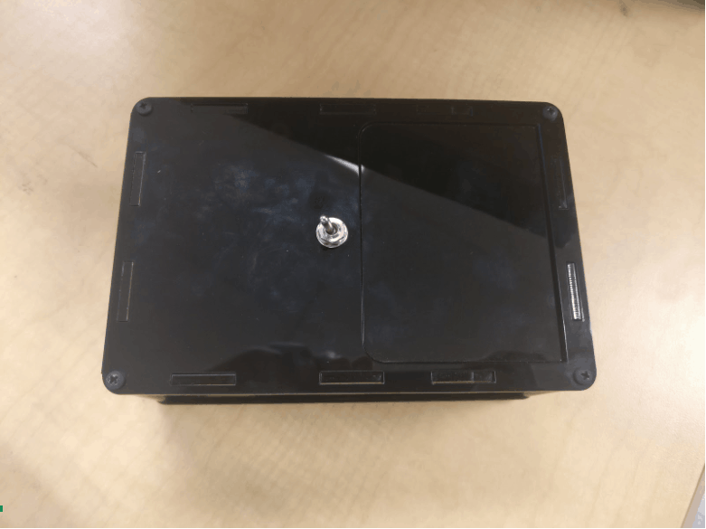
For my starter project, I built the Useless Machine. The useless machine works by flipping a lever and soon after the lever is flipped a mechanic arm comes out from the box and flips the lever back to its original position. This causes the arm to retract back into the box. There are a few main components of the Useless Machine: the lever, the snap switch, the motor, the arm, the PCB, the battery pack, the LED, and the resistors.