RC Robot Tank
My project is a RC Robot Tank where I controlled an Arduino through my own programming. The Arduino is connected to a PS2 controller and a motor to control the movement of the tank. And finally, I built a tank frame by putting smaller and cute pieces together, holding everything in.
| Engineer | School | Area of Interest | Grade |
|---|---|---|---|
|
Duly O. |
KIPP NYC College Prep |
Robotics |
Incoming Junior |
SECOND MILESTONE
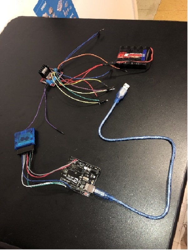
For my second milestone, I programmed two motors to go forward, backward, turn left, and turn right. At first, I connected my Arduino to my L298n with male jumper wires. L298n is a motor shield that helps control the speed and the direction of the motors. The L298 has a H-Bridge which is an electronic circuit which switches the polarity of a voltage applied to a load, controlling the motion and the direction of the motors. In order for the motors to move forward I would have to close A and D switches and for reverse you would have to close B and C. I then connected black and red male jumper wires from the L298n to the 2000mah battery with two red and black male cords powering the board. After that I connected male jumper wires from the L298n to the actual motors, and soldered them. Through connecting my Arduino to my computer I programmed some code, creating functions and loops, instructing my motors to move in the direction I proposed. In my functions I defined the directions in which the motors should turn, like for forward, backward, right and left. Then I created loops, creating a continuous pattern I wanted it to go. This milestone wasn’t as challenging as I thought it was going to be but one minor problem is that my PS2 controller no longer works so now I have to make my own controller which will be pretty cool. My 3rd milestone is quite easy and I expect to start today and hopefully finish it.
FIRST MILESTONE
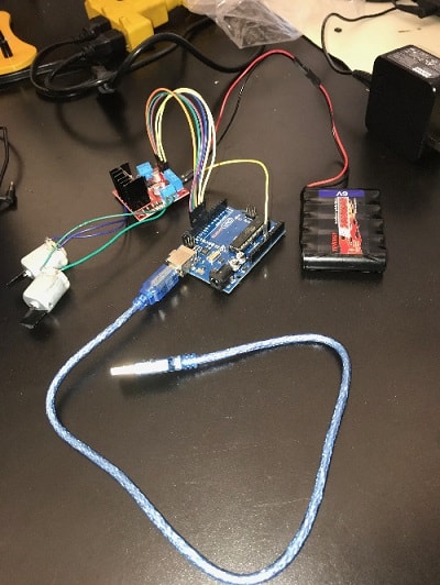
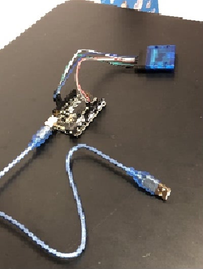
For my first milestone, my goal was to connect my arduino to my PS2 controller. In order to start this process my Arduino to my wireless PS2 controller, I used male to female wires to connect my receiver to the arduino. The controller has a wireless connection to the receiver, which sends information to the digital pins which are inputs and outputs on the Arduino. The PS2 library has built in functions that interprets which buttons are being pressed. Currently it responds and prints to the serial monitor which is a connection between your computer and the arduino where you can receive or send messages. In my next milestone, I will make the functions connect to the motors. Then I proceeded to connect a power cord to my laptop, opening up Arduino and uploading a set of code that allows me to test whether the controller is connected to the Arduino. The code helped print what was happening every time I interacted with the controller, when I pressed the down d’pad, it prints on the serial monitor. It states that it was pressed and the amount of pressure I put onto the d’pad. Other functions that are present is that when you move the joystick, you can find out the direction of it and whether a button is being held down or pressed. The library has specific booleans for each button and joystick, and has functions whether an action is present.
This code means a button on the d’pad is pressed it prints out on the serial monitor that the button is held and how hard it has been pressed.
In order for this to work, you have to connect wires from the receiver to the arduino using copper wires or male to female wires. The wires help facilitate a electrical connection between the receiver and the arduino. With a power cable I connected the arduino to my laptop, allowing me to access arduino and make sure that there was a connection between both the receiver and the arduino present. Through programming code, I was able to use the buttons and the joysticks, to print out some messages when interacting with the controller. The code I used in my arduino told me when a button was pressed, when it was held, released, when I changed buttons,the pressure in which I held the buttons and the joystick values.
STARTER PROJECT
My starter project was the Simon Says. In the game, light emitting diodes (LEDs) project light patterns that I had to replicate through pressing buttons of the order that was presented. A diode is an electronic component that conducts electricity in one direction, more over electrons and holes move across the junction in opposite directions and a current flows. Light emitting diodes specifically release light when electricity runs through the material inside. The game displays color patterns consisting of orange, blue, green and red. The game lights these in a specific pattern. You have to press buttons correlated to the colors and replicate what patterns you saw. There is a resistor that helps conduct electricity throughout the circuit board. On the Simon says is a micro controller, the brain of the circuit board.The patterns are all controlled by the ATMega which is the central control, controlling the piezo buzzer and colors. A capacitor stores and releases electric charge that helps decouple parts of an electrical network from another. In this project specifically, the capacitor helped smooth out electrical output. The capacitor also helps control kinetic energy. Also, there is a piezo buzzer which makes sounds for the lights. The Simon says controller is powered by AA batteries and is held together by screws and standoffs. I learned that I should be patient especially when soldering because that was the main source of my problems, also I learned to always follow directions, making sure that I have not messed anything up.
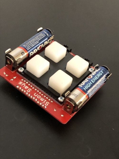
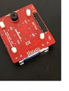
The Simon Says Project including the buttons, the batteries and the on and off switches
HOW IT WORKS
The Simon says game was powered by double AA batteries as the power source. The 2 0.1uF capacitors help store an electric charge around the circuit board and stabilize the current. The 10k resistors facilitated conduction of electricity throughout the board. The 4 LEDs help display the colors that you see and the noise is controlled by the piezo buzzer. All of this is controlled by the ATMega micro controller sending signals and instructions to all of the parts to then create the patterns and sounds that make up the Simon says game.
Simon Says Robot displaying the piezo buzzer and the micro controller